
Structure and method of manufacture for acoustic resonator using improved fabrication conditions, perimeter structure modifications, and thin film transfer process

a manufacturing method and acoustic wave technology, applied in the field of electronic devices, can solve the problems of reducing the performance of the rf, the complexity of the driving rf of smartphones, and the limitations of conventional rf technology, so as to improve the quality factor (q) of the resonator, improve the performance of the resonator, and improve the crystalline quality

Active Publication Date: 2021-04-08
AKOUSTIS INC
View PDF0 Cites 0 Cited by
  • Summary
  • Abstract
  • Description
  • Claims
  • Application Information

AI Technical Summary

Benefits of technology

The present patent provides a method for manufacturing an acoustic resonator or filter device using device layers and cavities with varying geometric areas. This method can increase device performance metrics by using specific dimensional ratios and ion implantations. The method can also include forming energy confinement structures around metal electrodes and using perimeter structures to improve device performance. Additionally, the method can use a thin film transfer process to improve the crystal quality of a polycrystalline piezoelectric film. The method is simple and cost-effective and can create reliable single crystal based acoustic filters or resonators.

Problems solved by technology

Coexistence of new and legacy standards and thirst for higher data rate requirements is driving RF complexity in smartphones.
Unfortunately, limitations exist with conventional RF technology that is problematic, and may lead to drawbacks in the future.

Method used


Image

  • Structure and method of manufacture for acoustic resonator using improved fabrication conditions, perimeter structure modifications, and thin film transfer process
  • Structure and method of manufacture for acoustic resonator using improved fabrication conditions, perimeter structure modifications, and thin film transfer process
  • Structure and method of manufacture for acoustic resonator using improved fabrication conditions, perimeter structure modifications, and thin film transfer process

Examples


Embodiment Construction

[0116]According to the present invention, techniques generally related to electronic devices are provided. More particularly, the present invention provides techniques related to a single crystal acoustic resonator using wafer level technologies. Merely by way of example, the invention has been applied to a resonator device for a communication device, mobile device, computing device, among others.

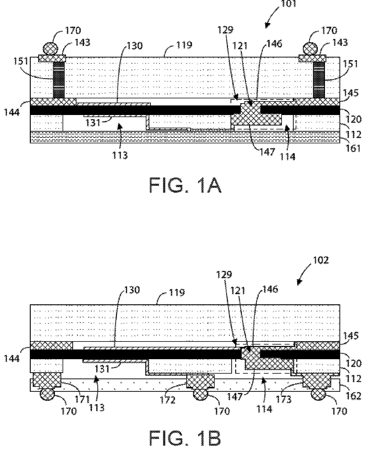
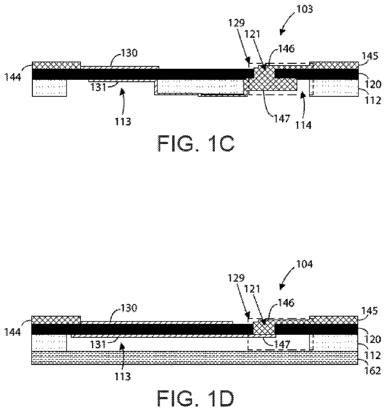
[0117]FIG. 1A is a simplified diagram illustrating an acoustic resonator device 101 having topside interconnections according to an example of the present invention. As shown, device 101 includes a thinned seed substrate 112 with an overlying single crystal piezoelectric layer 120, which has a micro-via 129. The micro-via 129 can include a topside micro-trench 121, a topside metal plug 146, a backside trench 114, and a backside metal plug 147. Although device 101 is depicted with a single micro-via 129, device 101 may have multiple micro-vias. A topside metal electrode 130 is formed overlyi...


PUM

PropertyMeasurementUnit
thicknessaaaaaaaaaa
diameteraaaaaaaaaa
diameteraaaaaaaaaa

Abstract

A method of manufacture for an acoustic resonator or filter device. In an example, the present method can include forming metal electrodes with different geometric areas and profile shapes coupled to a piezoelectric layer overlying a substrate. These metal electrodes can also be formed within cavities of the piezoelectric layer or the substrate with varying geometric areas. Combined with specific dimensional ratios and ion implantations, such techniques can increase device performance metrics. In an example, the present method can include forming various types of perimeter structures surrounding the metal electrodes, which can be on top or bottom of the piezoelectric layer. These perimeter structures can use various combinations of modifications to shape, material, and continuity. These perimeter structures can also be combined with sandbar structures, piezoelectric layer cavities, the geometric variations previously discussed to improve device performance metrics.

Description

CROSS-REFERENCES TO RELATED APPLICATIONS[0001]The present application claims priority to and is a continuation-in-part application of the following patent applications: U.S. patent application Ser. No. 16 / 136,158, filed Sep. 19, 2018, which is a continuation of U.S. patent application Ser. No. 15 / 342,061, filed Nov. 2, 2016, now U.S. Pat. No. 10,110,189, which is a continuation of U.S. patent application Ser. No. 15 / 341,218, filed Nov. 2, 2016, now U.S. Pat. No. 10,110,190; and U.S. patent application Ser. No. 16 / 433,849, filed Jun. 6, 2019, which is a continuation of U.S. patent application Ser. No. 15 / 784,919, filed Oct. 16, 2017, now U.S. Pat. No. 10,355,659, which is a continuation-in-part of U.S. patent application Ser. No. 15 / 068,510, filed Mar. 11, 2016, now U.S. Pat. No. 10,217,930. The present application also incorporates by reference, for all purposes, the following concurrently filed patent applications, all commonly owned: U.S. patent application Ser. No. 14 / 298,057, fi...

Claims


Application Information

Patent Timeline
Patent Type & Authority Applications(United States)
IPC IPC(8): H03H3/02H03H9/02H03H9/05H03H9/10H03H9/13H03H9/56H03H3/04H03H9/17
CPCH03H3/02H03H9/02118H03H9/0514H03H9/1035H03H9/132H03H9/568H03H2003/0414H03H9/131H03H9/133H03H9/171H03H9/564H03H9/174H03H2003/0428H03H3/04H03H2003/023H03H2003/025
Inventor VETURY, RAMAKRISHNAFELDMAN, ALEXANDER Y.HODGE, MICHAEL D.GEISS, ARTBOOMGARDEN, MARK D.LEWIS, MICHAEL P.PATEL, PINALKIM, DAE HOWINTERS, MARYSHEALY, JEFFREY B.
Owner AKOUSTIS INC
Learn More