Reel-to-Reel Lamination Methods and Devices in FPC Fabrication

a technology of flexible printed circuit and lamination method, applied in the direction of manufacturing tools, conductive material removal by irradiation, printed element electric connection formation, etc., can solve the problems of not addressing all environmental issues and cost-effectiveness issues, requiring manual intervention, and affecting the effect of embossing

Active Publication Date: 2021-03-25
MANAFLEX LLC
View PDF0 Cites 0 Cited by
  • Summary
  • Abstract
  • Description
  • Claims
  • Application Information

AI Technical Summary

Benefits of technology

[0011]In one aspect combinable with the general implementation, a novel laser ablation process to create a circuitry pattern in a reel-to-reel process and / or within a reel-to-reel machine where a sheet material is continuously fed into the reel-to-reel machine is disclosed. The laser ablation is contemplated to replace the need for chemical etching which can be costly and environmental hazardous. Contemplated laser ablation process eliminates the need to chemically wash away metal.
[0016]Further downstream the reel-to-reel conveyor system, the UV debonding sheet can be peeled away from the metal foil, effectively removing the negative material (which is adhered to the UV debonding sheet) from the metal foil.
[0019]Further downstream the reel-to-reel conveyor system, the thermal debonding sheet can be peeled away from the metal foil, effectively taking the negative material with it.
[0024]The contemplated novel method to remove the negative material, or slugs, can allow for faster processing of thicker metal foils during fabrication. It also eliminates the need for chemical etching.
[0029]The herein disclosed novel sintering process can efficiently and cost-effectively prepare pads on various different types of metal foil on the fly. It should be noted that the sintering process can take place either before or after circuitry patterns have been formed. The process generally includes using a paste (e.g., tin paste, nickel paste) that has metal particle fillers. In one way, the paste can be silkscreened directly onto the intended spots of pads on the metal foil. In another way, the paste can be silkscreened first onto a sacrificial liner plastic followed by transferring the paste reel-to-reel onto the intended spots on the metal foil. An anvil and a press roller can be used to press the paste onto the metal foil. However the paste is placed onto the metal foil, a laser can be used to irradiate the paste and remove the non-metal portion of the paste while also sintering the metal particles onto the intended spot of the pads on the metal foil, effectively plating the pads.
[0039]Optionally, before embossing the metal foils, a window can be created through whatever coverlay or substrate that may be in the way of laser welding so as to expose the intended locations for embossing and / or welding. This can improve the effectiveness of the embossing, thereby ensuring a successful welding process. Any known window-making processes can be implemented. Alternatively, a coverlay with pre-made windows are adhered to the metal foil, eliminated the extra step of creating windows.

Problems solved by technology

Such manufacturing process is stop and go, and may require manual intervention.
Known methods to produce a FPC include environmentally hazardous processes such as chemical etching and wasteful use of debonding sheets.
These disclosures, however, do not address all of the environment issues and cost-effectiveness issues.
Furthermore, where a definition or use of a term in a reference, which is incorporated by reference herein, is inconsistent or contrary to the definition of that term provided herein, the definition of that term provided herein applies and the definition of that term in the reference does not apply.

Method used


Image

  • Reel-to-Reel Lamination Methods and Devices in FPC Fabrication
  • Reel-to-Reel Lamination Methods and Devices in FPC Fabrication
  • Reel-to-Reel Lamination Methods and Devices in FPC Fabrication

Examples


Embodiment Construction

[0181]The different aspects of the various embodiments can now be better understood by turning to the following detailed description of the embodiments, which are presented as illustrated examples of the embodiments as defined in the claims. It is expressly understood that the embodiments as defined by the claims may be broader than the illustrated embodiments described below.

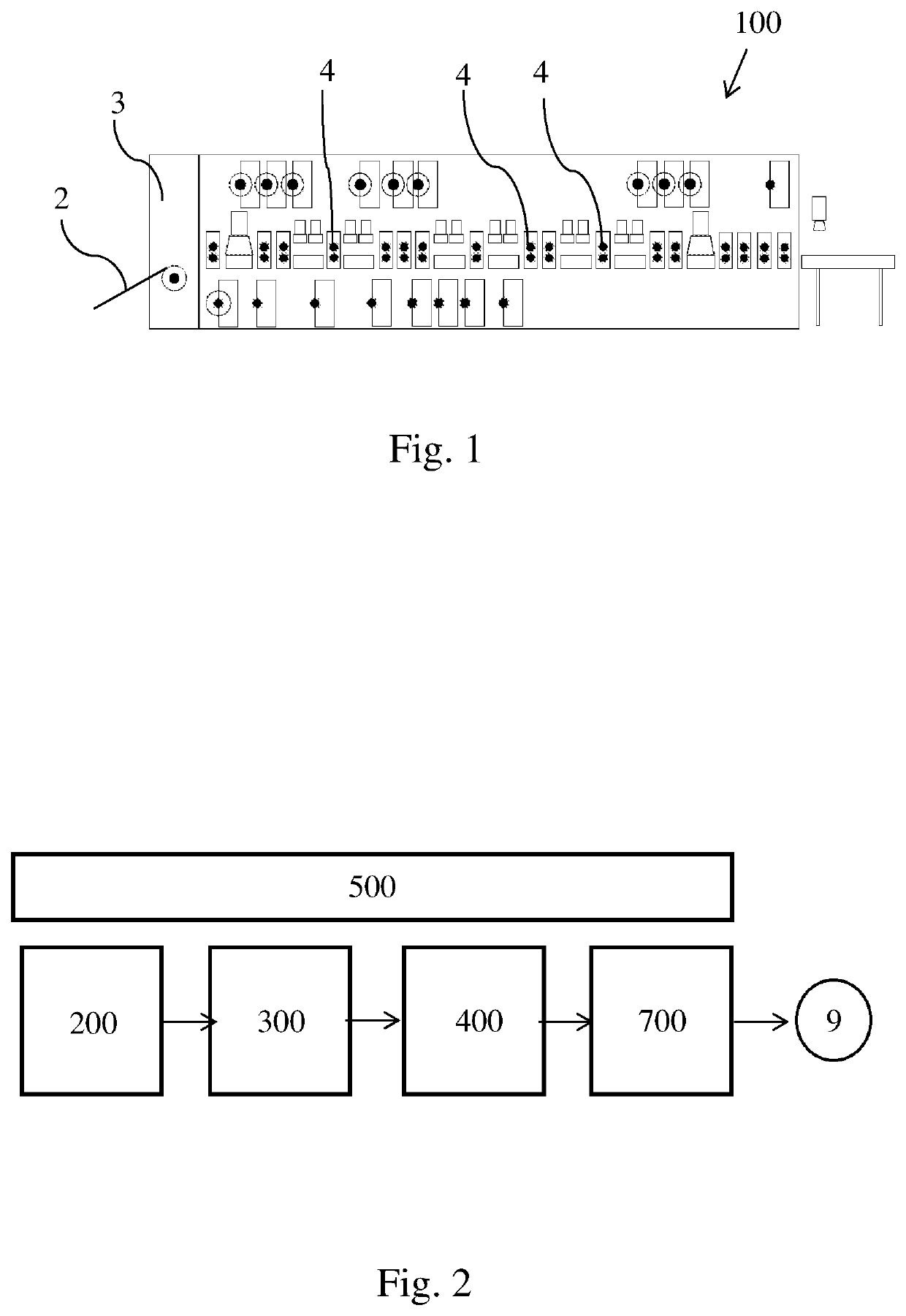
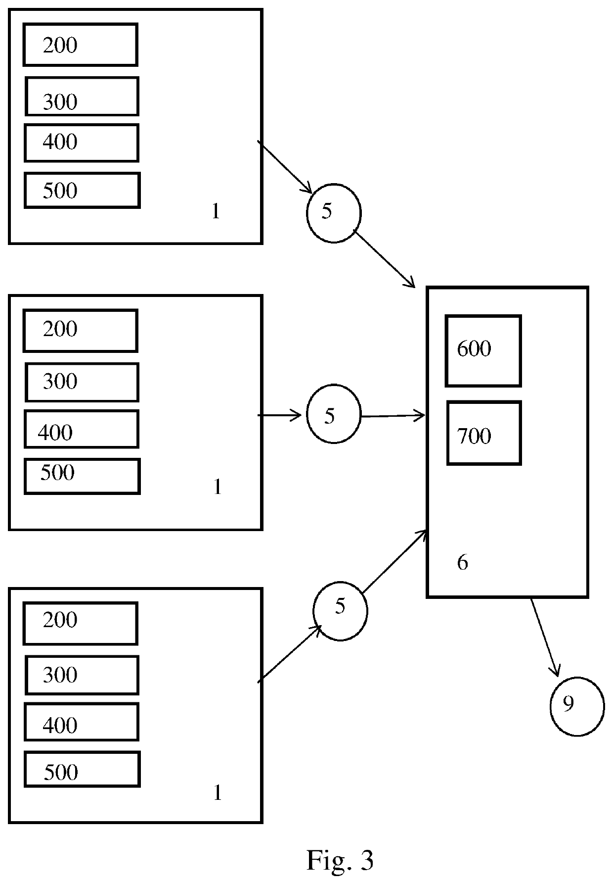
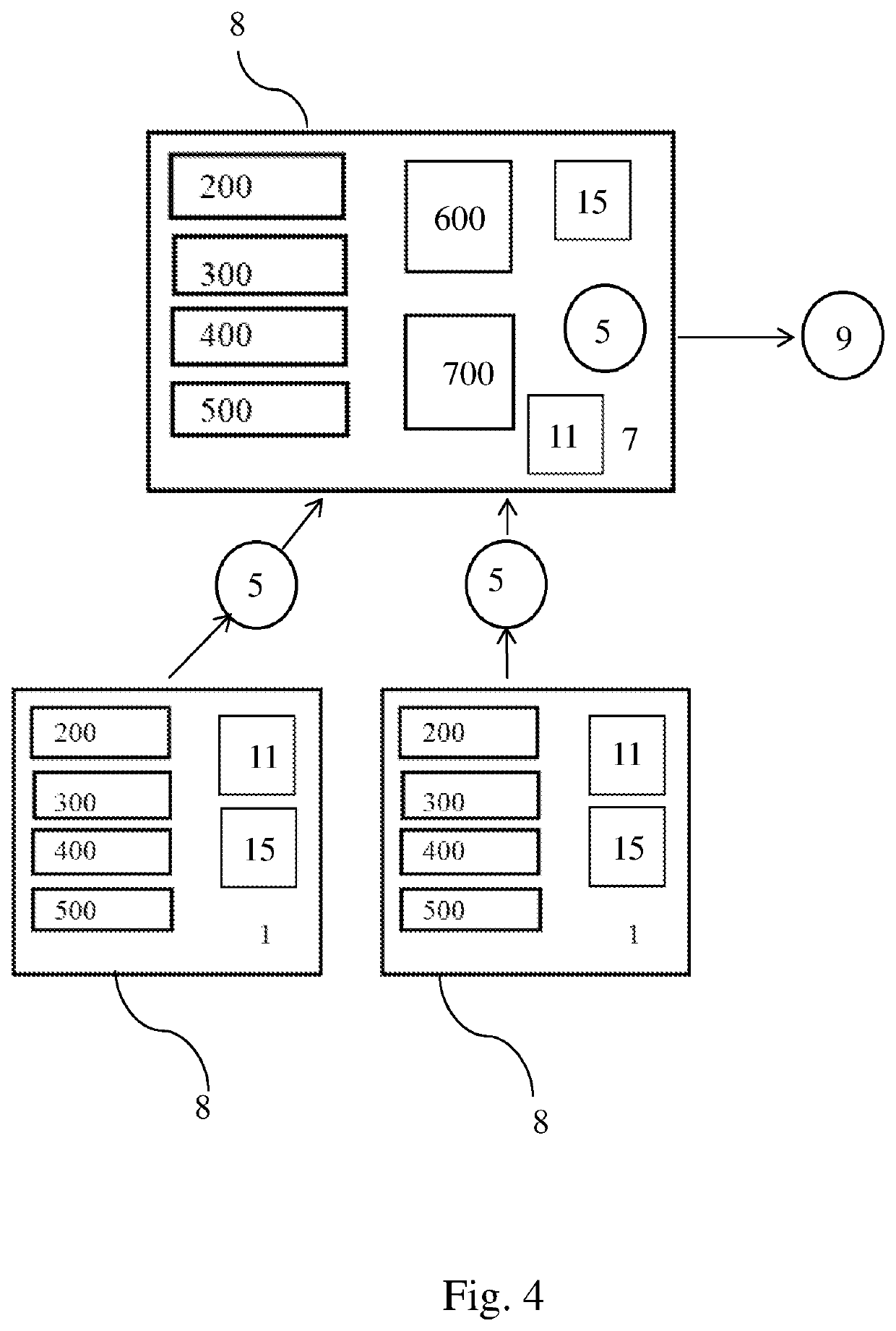
[0182]The inventor has discovered a novel method of fabricating a flexible printed circuit (FPC) that either entirely or partially eliminates the use of a gantry. As will be described in more details below, some of the processes can optionally include the use of a gantry. Other embodiments may supplement any of the herein disclosed reel-to-reel fabrication processes with the use of a gantry at some point of the fabrication process. For the most part, many of the below disclosed embodiments relate to a novel reel-to-reel fabrication process of a flexible printed circuit (FPC). The end product may be a single-lay...


PUM

PropertyMeasurementUnit
thicknessaaaaaaaaaa
flexibleaaaaaaaaaa
vacuumaaaaaaaaaa

Abstract

A reel-to-reel lamination method to laminate a metal foil or circuitry pattern on the fly. The method includes applying a UV laminate or thermoset laminate to the metal foil or the circuitry pattern reel to reel, and then apply a UV radiation or heat to the laminate. There can be an optional enclosure connected to a suction source. The enclosure can have a flexible bladder that physically compresses the laminate.

Description

CROSS-REFERENCE TO RELATED APPLICATIONS[0001]This application claims priority to, and is a non-provisional patent application of U.S. Provisional Patent Application No. 62 / 903,343, filed on Sep. 20, 2019, now pending, which is hereby incorporated by reference in its entirety.FIELD OF THE DISCLOSURE[0002]The present disclosure relates to renewable energy technologies in general, and more specifically a FPC (flexible printed circuit) fabrication processes for the electric vehicle industry.BACKGROUND OF THE DISCLOSURE[0003]Known methods to produce a FPC (flexible printed circuit) include using a gantry. Such manufacturing process is stop and go, and may require manual intervention.[0004]There is a continuing need for faster ways to produce a FPC.[0005]Known methods to produce a FPC include environmentally hazardous processes such as chemical etching and wasteful use of debonding sheets.[0006]There is a continuing need for environmentally friendlier and / or more cost-effective ways to pr...

Claims


Application Information

Patent Timeline
Patent Type & Authority Applications(United States)
IPC IPC(8): H05K3/46H05K3/00H05K1/03B23K26/08H05K3/02
CPCH05K3/4635H05K3/0097H05K2203/1545B23K26/0846H05K3/027H05K1/0393H05K2203/085H05K2203/107H05K3/046H05K3/1283H05K2203/1131H05K2203/081H05K2203/082H05K2203/0191H05K3/247H05K3/025H05K2201/0355H05K2201/10416H05K13/0417B23K26/082B23K2103/18B23K2101/42B23K26/16B23K26/38H05K3/0026H05K1/0277H05K1/092H05K1/112H05K3/1216H05K3/4007H05K3/42H05K3/4644H05K2203/16H05K3/041H05K3/4655H05K3/4658H05K2203/0195H05K2203/063H05K2203/1105H05K2203/128H05K2203/1453
Inventor LANE, ROBERT CLINTON
Owner MANAFLEX LLC
Why Eureka
Try Eureka