Image forming apparatus
a technology of forming apparatus and fpot, which is applied in the direction of electrographic process apparatus, instruments, optics, etc., can solve the problems of image defect, operation sound and power consumption caused by rotation operation, and achieve the effects of reducing fixing-set marks, shortening fpots, and suppressing operation sound and/or power consumption
- Summary
- Abstract
- Description
- Claims
- Application Information
AI Technical Summary
Benefits of technology
Problems solved by technology
Method used
Image

Examples
first embodiment
Functional Block in First Embodiment
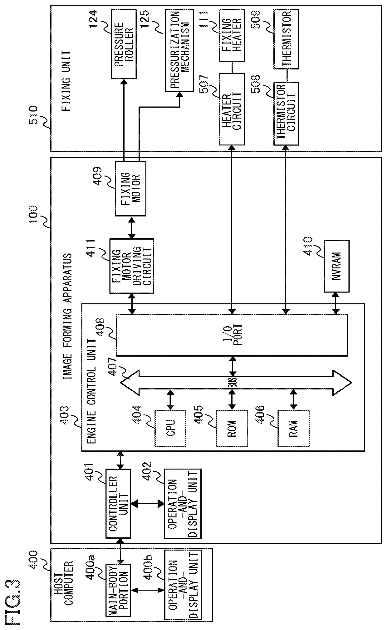
[0055]Functions of the engine control unit 403 will be described with reference to the functional block diagram of FIG. 4. The functions of the engine control unit 403 are executed by the CPU 404 in accordance with a program stored in the ROM 405 and data stored in the RAM 406.
[0056]The engine control unit 403 includes an image-forming control portion 2001 that has functions for forming images. The image-forming control portion 2001 determines image-forming conditions, such as a speed of feeding and conveying operations, a transfer voltage value, and a fixing temperature, in accordance with a type (hereinafter referred to as a sheet type) of the recording material; and manages the execution of the electrophotographic process performed by the image forming portion 500. In addition, the image-forming control portion 2001 instructs a toner-image heating controller 2002 to perform a heating operation, and a recording-material conveyance controller 200...
first modification
[0074]The pressure release control may be performed depending on an elapsed time from the completion of sheet passing, instead of the set value (specified number of times) that is an upper limit of the number of times of the nip-position change control as descried in the first embodiment. For example, in the type A of the fixing-set mark prevention control, the nip-position change control is performed in a time period from when a sheet passing completes, until when a threshold time (for example, 40 minutes) elapses; and the pressure release control is performed after the 40 minutes have elapsed. In this case, the time setting of 40 minutes (that is a time period in which the first pressurization state is kept after the completion of sheet passing) may be stored in a storage medium such as a ROM, instead of the specified number of times, and the time setting may be read by the CPU when the CPU executes the fixing-set mark prevention control. Also in such a case, like the operation of...
second modification
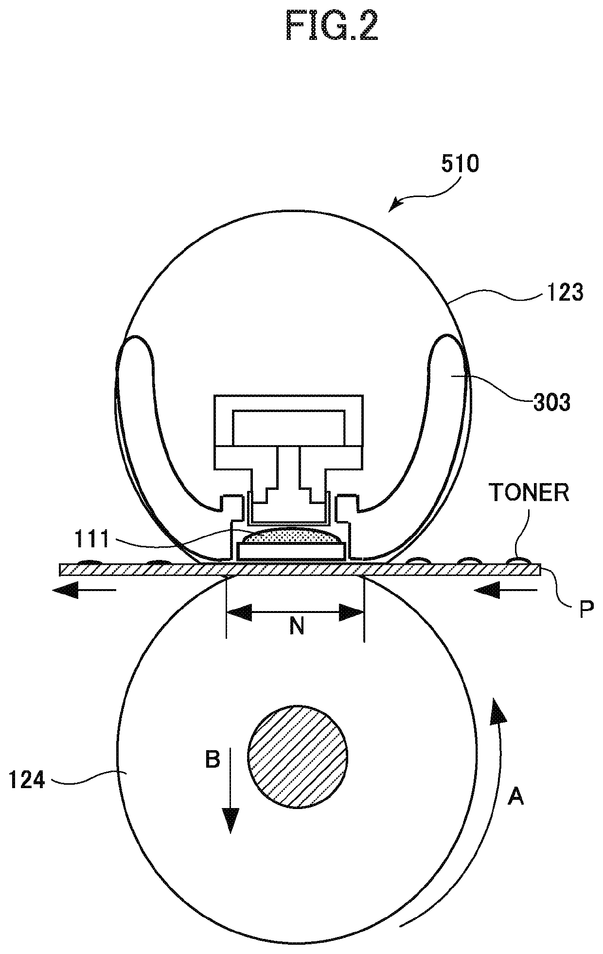
[0075]In the first embodiment, the description has been made for the configuration that uses an endless fixing film as a fixing member. However, the present embodiment is also effective in cases where the second rotary member is a fixing roller having an elastic layer, and where both of the first rotary member and the second rotary member are endless films or belts. This is because also in these cases, the deformation caused by the pressurization that leads to the fixing-set mark may occur in at least one of the first rotary member and the second rotary member, and the fixing-set mark prevention control of the present embodiment can reduce the fixing-set mark and achieve both of shortening the SFPOT and suppressing the operation sound and the power consumption.
Second Embodiment
[0076]A second embodiment uses a method of analyzing a trend of operating conditions of the image forming apparatus from the history of operations of the image forming apparatus, and changing the type of the f...
PUM
 Abstract
Description
Claims
Application Information
 - R&D
- Intellectual Property
- Life Sciences
- Materials
- Tech Scout
- Unparalleled Data Quality
- Higher Quality Content
- 60% Fewer Hallucinations
Browse by: Latest US Patents, China's latest patents, Technical Efficacy Thesaurus, Application Domain, Technology Topic, Popular Technical Reports.
© 2025 PatSnap. All rights reserved.Legal|Privacy policy|Modern Slavery Act Transparency Statement|Sitemap|About US| Contact US: help@patsnap.com