
Casing for a rotor of a tableting machine

a tableting machine and rotor technology, which is applied in the field of casings for tableting machines, can solve the problems that the material for compression that has been metered out cannot be returned to the filling device by the device itself, and the service life of the tableting machine is adversely affected, and the compression material is often undesirable on the die tabl

Inactive Publication Date: 2021-03-25
KORSCH AG DE
View PDF3 Cites 0 Cited by
  • Summary
  • Abstract
  • Description
  • Claims
  • Application Information

AI Technical Summary

Benefits of technology

The proposed device can generate an air flow in the tableting machine to remove excess tableting material and create a vacuum without the need for additional hoses or tubes. The device can be used in a flexible way with multiple annular channels, allowing for separate dedusting of compression materials. The result is better extraction with lower suction power and improved efficiency.

Problems solved by technology

As is known from the prior art, when tableting material is compressed to form pellets, dust can form, i.e., undesired particles move around in the compression chamber of the tableting machine and become deposited on internal surfaces of the compression chamber of the tableting machine and / or penetrate into operative areas of the tableting machine where they can impact operation of the tableting machine or can adversely affect the service life of the tableting machine.
Since these filling devices do not use motorized aids to improve the filling properties, this is the most gentle method of conveying the material for compression into the die bore without the structure of the powder or the granulate, i.e., the tableting material, being destroyed by excessive friction and movement.
The disadvantage of gravity filling devices is that material for compression that has been metered out cannot be returned to the filling device by the device itself.
As a result, compression material is frequently undesirably found on the die table, and the corresponding grains or the powder may be thrown outward by centrifugal force, especially when the rotor of the tableting machine is rotating at high speeds, and may accumulate as waste within the machine.
The die table draws the fine powder particles beneath the filling shoe plate through this gap, so that in this case too, a resilient scraper is required to guide the escaping material into the material collecting channel, as otherwise the material loss would be too great.
Then when compression material exits the filling devices and remains on the die table, this material is forcibly thrown outward on the die table by the tremendous centrifugal force and can fall into the compression chamber of the tableting machine in an uncontrolled manner.
The compression tools themselves are another source of material losses.
This soiling is undesirable because it decreases the service life and thus the productivity of the rotary press and increases wear and tear on the mechanical components.
Another critical source of dust in the tableting machine is the area in which the upper punches descend into the filled dies to the right of the filling device.
The upper and lower punches are preferably located in the cylindrical part of the die bore, but disadvantageously do not completely trap the compression material in the die bore, since the diameter of the upper and lower punches is 0.2 mm smaller than the diameters of the die bores.
As a result, the air trapped in the compression material disadvantageously escapes upward and downward through this gap at very high speeds.
As a result of this considerable flow of air, the very fine particles in the vicinity of the gap, which are preferably smaller than 0.1 mm, are entrained and thus make their way into the area above and below the die table, which leads to further soiling of the rotary press.
These fine airborne particles are particularly hazardous because they can work their way into the punch guides and thereby significantly reduce the service life and thus the productivity of the rotary press.
Since the nozzles are usually positioned individually, spaces in which undesirable dust can further accumulate are created between the nozzles.
Due to the large spaces between the extraction nozzles, however, soiling of the rotary press cannot be effectively prevented despite the suction.

Method used


Image

  • Casing for a rotor of a tableting machine
  • Casing for a rotor of a tableting machine
  • Casing for a rotor of a tableting machine

Examples


Embodiment Construction

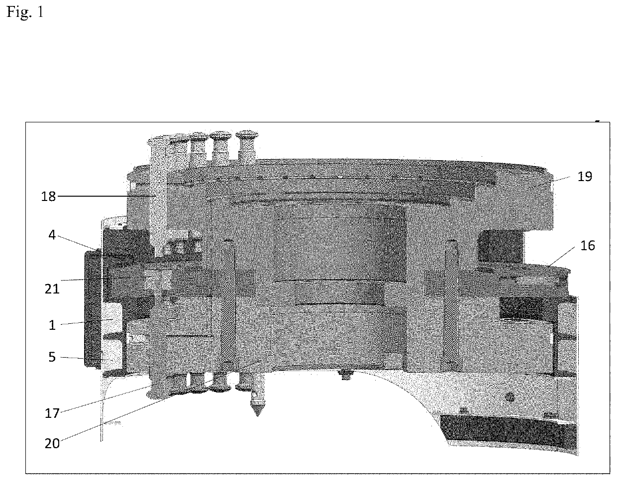
[0019]The object is attained by the features of the independent claims. Advantageous embodiments of the invention are described in the dependent claims. According to the invention, a casing is provided for a rotor of a tableting machine, the casing comprising at least one integrated annular channel, and the casing further comprising suction means with which a rotating air flow can be generated in the at least one annular channel that is adapted to entrain substantially all of the excess tableting material and remove it from a compression chamber of the tableting machine.

[0020]In a preferred embodiment, the invention relates to a device for removing excess tableting material from a compression chamber of a tableting machine, in which compressed pellets are produced in the compression chamber by bringing upper punches and lower punches together in openings in a die table, the die table being held by a rotor. The device is characterized in that the rotor comprises a casing in which at ...


PUM


Abstract

A casing for a rotor of a tableting machine is disclosed. A method for removing excess tableting material from a tableting machine is also disclosed.

Description

[0001]The invention relates to a casing for a rotor of a tableting machine. In a further aspect, the invention relates to a method for removing excess tableting material from a tableting machine.GENERAL BACKGROUND AND PRIOR ART[0002]Tableting machines are used in many branches of industry to compress powdered or granulated materials into solid compressed pellets. In the pharmaceuticals industry, this may involve numerous forms of tablets, in the chemicals industry it may be dishwashing detergent tablets, toilet cleaner tablets, fertilizer sticks or catalysts, and in the foods industry it may be peppermint tablets or glucose tablets, for example. The sub-class of rotary presses was developed primarily for producing solid and stable compressed pellets in large quantities from powdery or granulated compression materials that are dry, pourable, and free-flowing, within extremely narrow weight tolerances.[0003]For the purposes of the invention, this material for compression is preferably...

Claims


Application Information

Patent Timeline
IPC IPC(8): B30B11/08B30B15/00
CPCB30B11/08B30B11/34B30B15/0082B30B15/32
Inventor MIES, STEPHANWEISSBACH, THOMAS
Owner KORSCH AG DE
Learn More