
Method for dynamically configuring entities of a communications network for routing data from a visitor terminal

a dynamic configuration and data technology, applied in the field of access networks, can solve the problems of relatively difficult implementation of network sharing options, limited access to the second network, and high cost of operators to deploy their specific infrastructures, and achieve the effect of limiting the possibility of accessing the second network

Active Publication Date: 2021-03-18
ORANGE SA (FR)
View PDF0 Cites 1 Cited by
  • Summary
  • Abstract
  • Description
  • Claims
  • Application Information

AI Technical Summary

Benefits of technology

This patent describes a way to control the use of network resources by a visited network operator while still benefiting from the sale or leasing of those resources to another operator. The visited network operator can set a duration for the use of resources, which allows them to control their investments and take advantage of the resources of the other operator in case of temporary unavailability or lack of resources. The terminal should not try to attach to a network for which the operator of the first network has not or has no longer leased or reserved transmission resources. This prevents the sending of new configuration parameters when a network should no longer be used and saves network resources by avoiding the sending of access attempts by the terminal. The terminal with user credits should have the possibility of accessing the second network based on the quantity of these credits, which makes it possible to limit the possibilities of accessing the second network and to prevent a guest terminal from consuming too many resources of the second network.

Problems solved by technology

The pooling of mobile networks with inter-operator roaming has become a strategic challenge for operators in order to reduce their network coverage costs, especially in black spots, that is to say areas not covered by networks, and for which it may be expensive for operators to deploy their specific infrastructures.
This network sharing option is relatively difficult to implement due to the security and administrative problems that this entails for clients and operators.
This roaming service may however lead to service restrictions for the client of a (“visited”) operator different from the one (“home”) owning the communication network.
This second option may lead to a connection problem for the visiting client, in particular if the agreement with the operator that he has selected for connection is less rich in terms of functions or limited to certain time slots.
To date, it is thus not possible to establish a roaming agreement automatically and on the fly: it is necessary to use the respective information systems of the operators.
However, in certain situations, in particular if the networks available at a given location are managed by operators with which a “home” operator has not concluded a contract, clients may not have connectivity even though access networks may be available.
The problem also arises if operators who have signed a contract operate networks that are not available at a given time.
In this case, the “visiting” client will not be able to connect to an operator network that has not concluded a contract with the operator of the “home” network.
Furthermore, in mobile networks up to the 4G (Fourth Generation) generation, a terminal is not able to attach to a network different from its “home” network if the latter is available.
In particular, there is no mechanism for the dynamic and unscheduled implementation of an inter-operator roaming solution, comprising a process of dynamically updating the network equipments in order to authorize the connection of a “visiting” client.

Method used


Image

  • Method for dynamically configuring entities of a communications network for routing data from a visitor terminal
  • Method for dynamically configuring entities of a communications network for routing data from a visitor terminal
  • Method for dynamically configuring entities of a communications network for routing data from a visitor terminal

Examples


first embodiment

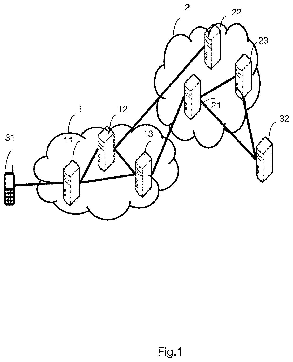
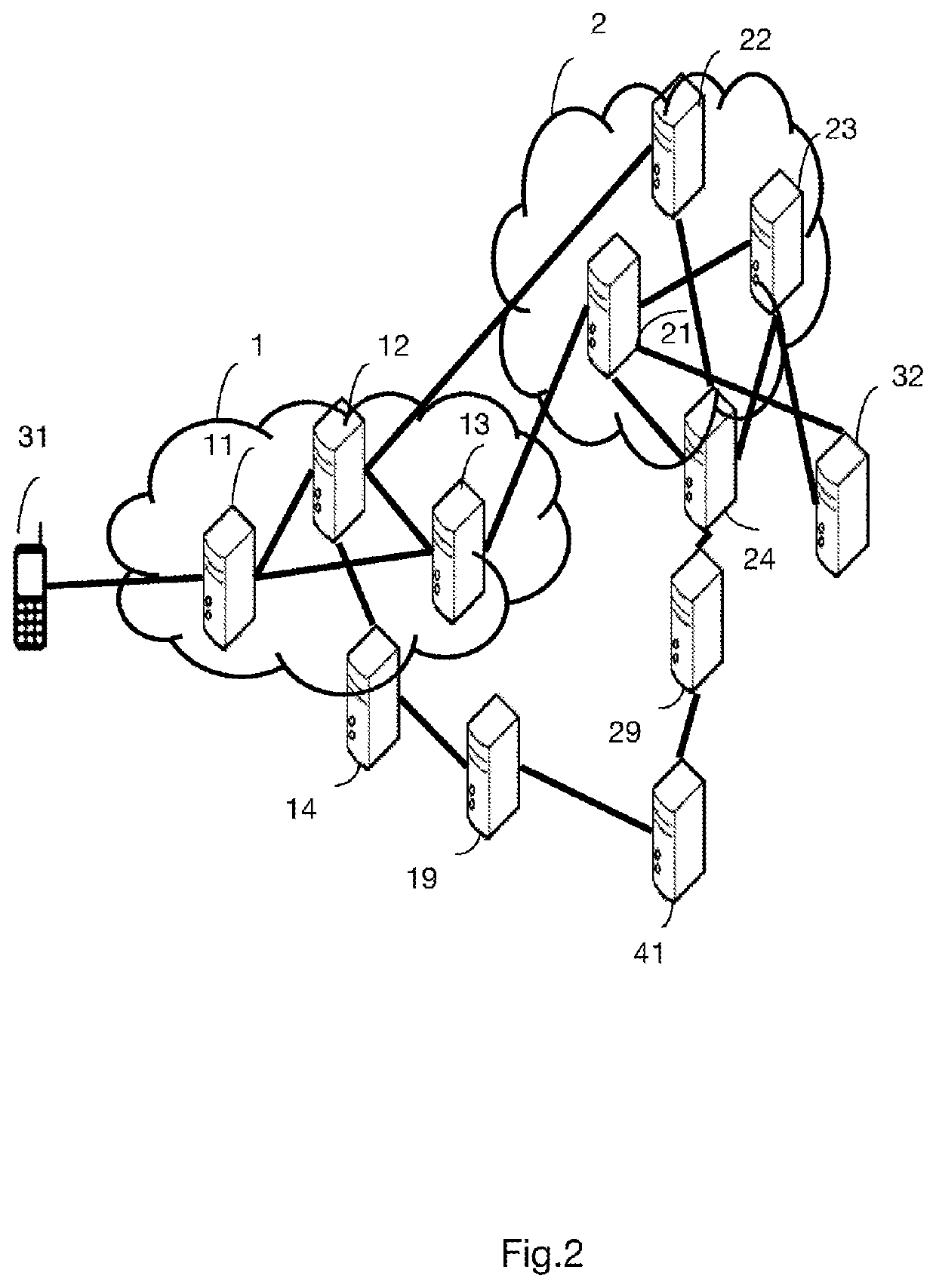
[0060]FIG. 2 shows an architecture of a roaming service between two communications network operators in which the configuration method is implemented, according to a

[0061]The following changes from FIG. 1 are taken into consideration in this FIG. 2.

[0062]According to one example, the user of the terminal 31 may purchase a roaming service via credits (also called tokens). The credits are available for example in the digital wallet of the user of the terminal 31, which is attached to the account of the user subscribed to the operator of the network 2 (Home). The terminal may use these credits on visited networks. It should be noted that the credits could also be used by the user to connect to the network 2 if the subscription to the operator of the network 2 involves providing a number of credits to attach to the network 2.

[0063]This FIG. 2 also differs from FIG. 1 through the addition of new entities. The entity 14 in the network 1 is a management entity of the network 1 whose purpos...

second embodiment

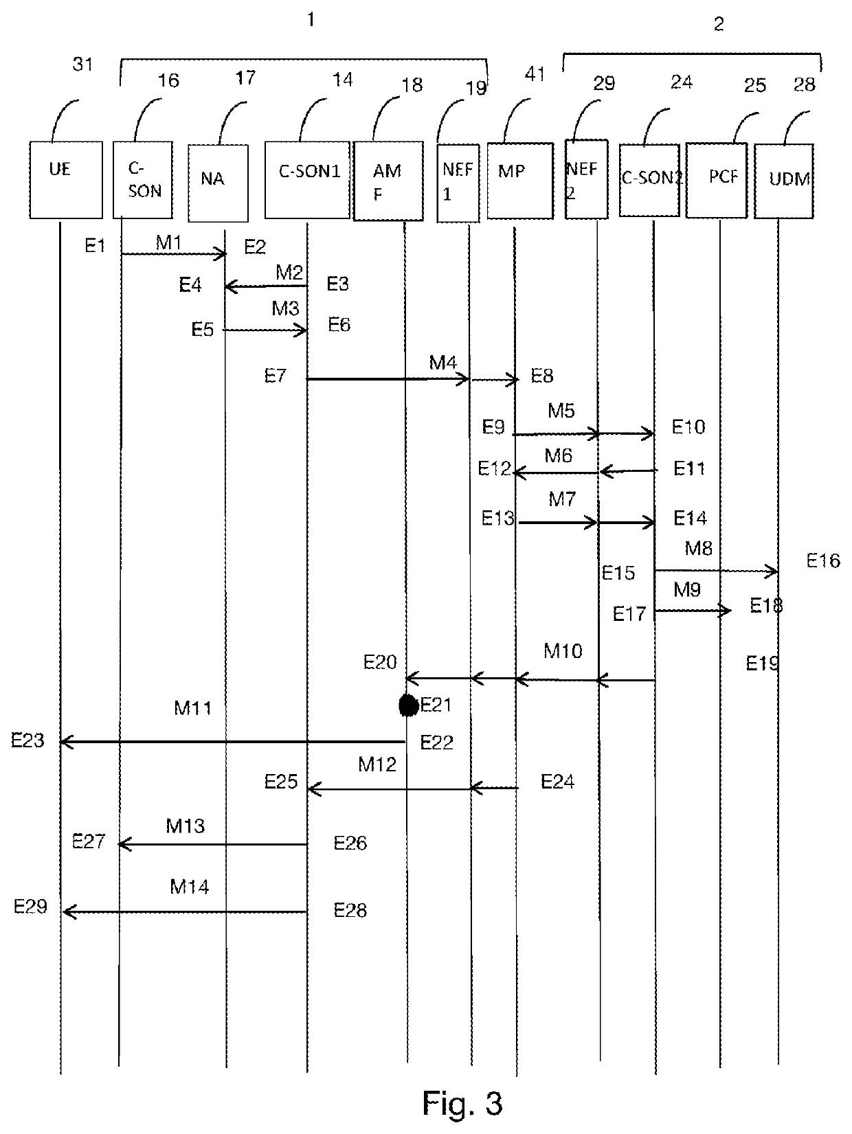
[0070]FIG. 3 shows an overview of the method for configuring a terminal, according to the invention. This embodiment is implemented in a 5G network architecture as defined in document 3GPP TS 23.501 (Version 12 / 2017).

[0071]In step E1, a C-SON (“Centralized Self-Organizing Network”) entity 16, managing the resources of the access networks of the network 1, transmits, to an NA (“Network Analytics”) entity 17, a message M1 comprising information regarding the radio antenna capacities of the access networks of the network 1.

[0072]The purpose of the C-SON entity 16 is to automatically update the configurations of the network equipments in order to balance the load and in particular optimize the use of the various equipments. This message M1 is transmitted periodically. A C-SON1 management entity 14 of the entire network 1, in step E3, transmits a message M2 comprising information regarding the terminals attached to the network 1 as well as the identifiers of these terminals to the NA ent...

third embodiment

[0092]FIG. 4 shows an overview of the method for configuring a terminal, according to the invention. Entities in the figure corresponding to the entities described in FIGS. 1 and 2 are identified by the same numbers in FIG. 4. In this FIG. 4, compared to FIG. 3, the network 1 does not have an NA entity 17.

[0093]Steps E′1 to E′14 are identical to steps E1 to E14 in FIG. 3, with the difference that there is no step E′3 to E′6 in FIG. 4 due to the absence of an NA entity. The entity 16 thus transmits statistics regarding the use of the access networks to the C-SON1 entity 14 in a message M′1, and the entity 14 transmits the information regarding the connected terminals and the availability or the lack of resources in a message M′4 transmitted to the entity 41.

[0094]Steps E′15 to E′18 are identical to steps E15 to E18, with the difference that the PCRF control entity 26 replaces the PCF entity and the HSS entity 22 replaces the UDM entity of FIG. 3, but taking their respective roles and...


PUM


Abstract

A method for configuring a terminal of a client user of an operator managing a first communications network. The method is implemented prior to the attachment of the terminal to a second communications network, for which transmission resources are temporarily used for routing data from the terminal to a remote server. The method includes receiving, from a control entity of the first network, a management instruction relating to the attachment of the terminal to the second network for a geographical zone. The method further includes configuring a data item relating to the control of the attachment of the terminal on the basis of the received management instruction, and transmitting, to the at least one terminal, at least one configuration parameter for attaching the terminal to the second network.

Description

1. FIELD OF THE INVENTION[0001]The application for invention lies in the field of access networks and relates to roaming techniques for a terminal on a set of access networks.2. PRIOR ART[0002]The pooling of mobile networks with inter-operator roaming has become a strategic challenge for operators in order to reduce their network coverage costs, especially in black spots, that is to say areas not covered by networks, and for which it may be expensive for operators to deploy their specific infrastructures. In particular in areas with a low population density, an operator more often than not deploys a mobile network primarily in order to provide connectivity to its clients, but also for clients of other operators who have not deployed infrastructure in the geographical area. One alternative option to this option consists in deploying a telecommunications infrastructure that is shared between several operators, each operator financing part of the infrastructure in accordance with an ag...

Claims


Application Information

Patent Timeline
IPC IPC(8): H04W8/18H04W60/00H04W12/04H04W12/08
CPCH04W8/18H04W12/08H04W12/04033H04W60/00H04W8/12H04W12/0433
Inventor MARJOU, XAVIERRADIER, BENOITFROMENTOUX, GAEL
Owner ORANGE SA (FR)
Learn More