Solar module mounting apparatus with edge to edge waterproofing capabilities

a solar module and mounting apparatus technology, applied in the direction of heat collector mounting/support, light and heating apparatus, photovoltaic supports, etc., can solve the problems of high cost, commercial disadvantage, and often expensive use of custom-built solar modules, so as to eliminate the need for an underlying roof, maximize solar exposure, and improve building aesthetics

Inactive Publication Date: 2021-03-11
WAKEMAN JOHN
View PDF0 Cites 0 Cited by
  • Summary
  • Abstract
  • Description
  • Claims
  • Application Information

AI Technical Summary

Benefits of technology

The present invention provides a solar roof design that has several advantages over other BIPV designs. Firstly, it does not require a roof, which makes maintenance and replacement easier. Secondly, it can cover the entire roof, maximizing solar exposure and improving building aesthetics. Thirdly, it allows for easy removal and replacement of individual modules without being blocked by other modules. Fourthly, it uses spacers to ensure consistent spacing and coverage of the modules, which results in a better overall width of the solar array. Finally, it includes pre-assembled components that make installation easier.

Problems solved by technology

Building Integrated PV is very unusual, about one percent of the market, as it typically costs much more than conventional solar installation techniques.
However, when used as a roof or other cladding, such apparatuses frequently have the disadvantage of requiring custom-built solar modules.
While these other inventions might function as designed, using them is much more costly and commercially disadvantageous than would be the case with a system which could fit “off the shelf” solar modules.
Additionally, many of these pre-existing designs are not well adapted for safe, easy access when maintenance or repair is needed in an area occupied by their solar array(s).
As a result, most existing BIPV systems only have provisions to interface at their edges with conventional roofing materials (rather than going all the way to an edge of the roof).
Any system which makes it difficult to install or maintain such an apparatus not only adds to labor costs, but it can be hazardous to service technicians or emergency personnel who need to work on it.
Additionally, existing designs often lack features which allow reproducible positioning of modules.

Method used


Image

  • Solar module mounting apparatus with edge to edge waterproofing capabilities
  • Solar module mounting apparatus with edge to edge waterproofing capabilities
  • Solar module mounting apparatus with edge to edge waterproofing capabilities

Examples


Embodiment Construction

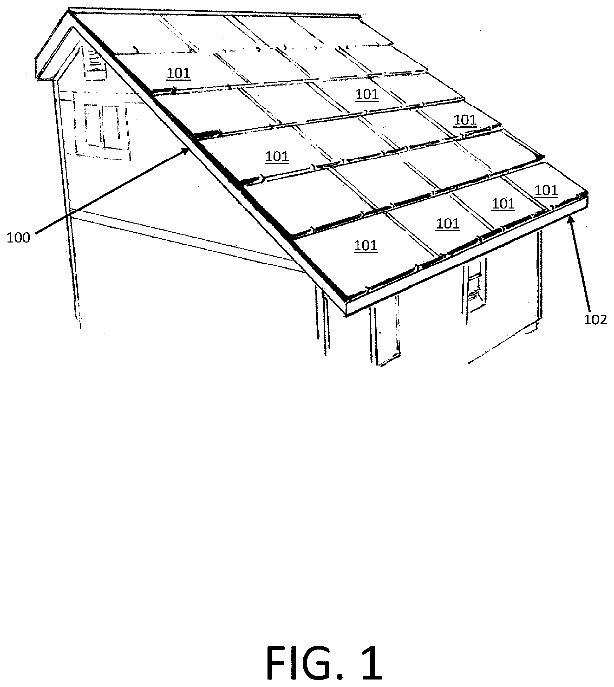
[0126]The following detailed description of the invention refers to the accompanying figures. The description and drawings do not limit the invention; they are meant only to be illustrative of example embodiments. Other embodiments are also contemplated without departing from the spirit and scope of the invention. Referring now to the drawings, embodiments of the invention are shown and disclosed. In this disclosure, the terms “solar panel” and “solar module” are interchangeable. In this disclosure, the terms “up-roof” and “down-roof” will be used to describe relative positions of components. For example, a solar module which is positioned further up a roof than a clamp will be referred to as an “up-roof module”, and a solar module positioned further down a roof than that same clamp will be referred to as a “down-roof module”.

[0127]FIG. 1 shows an example embodiment of the invention in the form of a roof assembly, which comprises horizontal joint assemblies, vertical joint assemblie...


PUM


Abstract

An apparatus is contemplated for creating a structure which simultaneously serves as both a building element and a photovoltaic power source. Components of the invention interface with modules which comprise photovoltaic solar panels. When used collectively, these modules are contemplated as comprising a replacement for a roof or other building component. When the present invention is used, a roof or other building component can be created without the need for a separate underlayment, and without the need for tiles or another outer waterproofing layer. This setup results in power generation, cost savings, and environmental advantages Additionally, embodiments of the invention comprise fixed stop elements which ensure correct placement of modules on a frame assembly. The invention could also include other elements, including water gutters, grab steps which facilitate access, and specially positioned border covers to protect and aesthetically cover wired regions of solar modules.

Description

[0001]The following continuation-in-part application claims the priority benefit of earlier application Ser. No. 16 / 919,105, filed on Jul. 1, 2020, which claims priority from earlier application Ser. No. 16 / 132,463, filed on Sep. 16, 2018.BACKGROUND OF THE INVENTION1. Field of the Invention[0002]The present invention relates to an apparatus for creating a structure which simultaneously serves as both a building element and a photovoltaic power source, known in the art as “Building Integrated Photovoltaic”, or “BIPV”.[0003]Solar electric (photovoltaic) generation is predicted to be a much greater part of a future mix of electrical generation techniques. A key to getting solar energy generation more widely adapted is to reduce costs. In doing so, people have often struggled to get every aspect of installation costs reduced. This invention attempts to “side-step” the typical methods of reducing cost by instead eliminating many construction and maintenance costs, rather than reducing th...

Claims


Application Information

Patent Timeline
Patent Type & Authority Applications(United States)
IPC IPC(8): H02S20/23H02S30/10E04D3/40E04D3/38
CPCH02S20/23E04D3/38E04D3/40H02S30/10E04B7/024E04D3/02E04D3/366E04D13/1585F24S20/67F24S25/636F24S2020/13F24S2025/022H02S30/00H02S20/26Y02B10/10Y02B10/20Y02E10/50
Inventor WAKEMAN, JOHN
Owner WAKEMAN JOHN
Why Eureka
Try Eureka