
Motor

a motor and motor body technology, applied in the field of motors, can solve the problems of increasing the number of molds, increasing the cost, and high material loss, and achieve the effect of improving insulation stability and simplifying the assembly process

Active Publication Date: 2021-02-25
LG INNOTEK CO LTD
View PDF0 Cites 3 Cited by
  • Summary
  • Abstract
  • Description
  • Claims
  • Application Information

AI Technical Summary

Benefits of technology

This patent describes a design that combines terminals with the same shape to connect two circuits. This design ensures accurate positioning of the terminals during the process of creating a bus bar and simplifies the assembly process. Additionally, the design allows for the terminals to have protruding portions that are evenly spaced, which improves insulation stability.

Problems solved by technology

In the case in which the terminals have various shapes, there are problems in that the number of molds is increased, a cost is increased, material loss is high, and a manufacturing process is complicated.
In addition, during a process of injection-molding the bus bar, there are problems in that errors in position of two terminals may easily occur, and it is difficult to visually check whether a position of the neutral terminal or the phase terminal is correct.

Method used


Image

  • Motor
  • Motor
  • Motor

Examples


Embodiment Construction

[0033]Hereinafter, exemplary embodiments of the present invention will be described with reference to the accompanying drawings in detail. Purposes, specific advantages, and novel features of the invention will be made clear from the exemplary embodiments and the following detailed description in connection with the accompanying drawings. In the description of the invention, when it is determined that detailed descriptions of related well-known functions unnecessarily obscure the gist of the invention, the detailed descriptions thereof will be omitted.

[0034]It will be understood that, although the terms “first,”“second,” etc. may be used herein to describe various elements, these elements should not be limited by these terms. These terms are only used to distinguish one element from another. For example, a first element could be termed a second element, and a second element could similarly be termed a first element without departing from the scope of the present invention. As used h...


PUM


Abstract

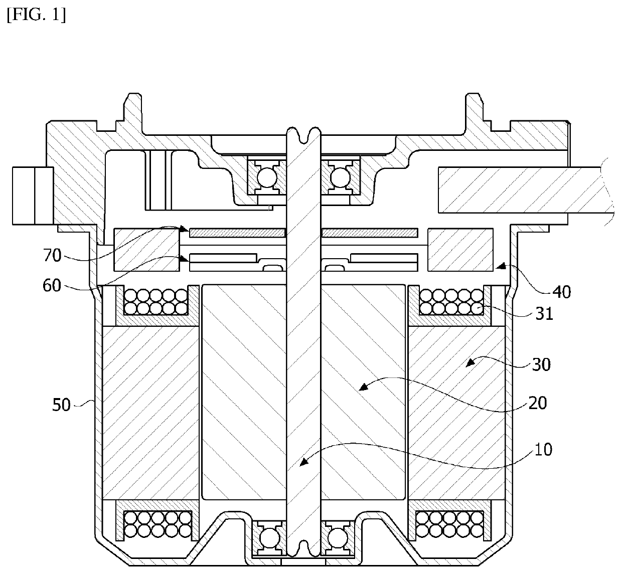
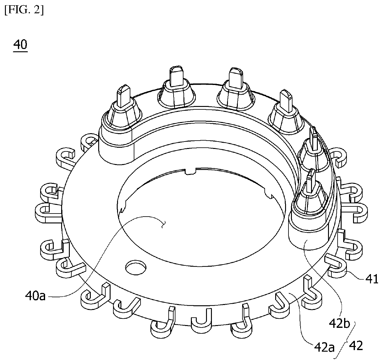
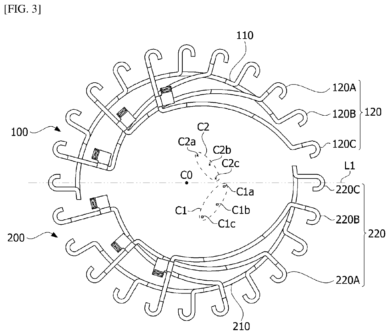
The present invention may provide a motor including a shaft, a rotor coupled to the shaft, a stator disposed outside the rotor, and a bus bar disposed on the stator, wherein the bus bar includes a terminal connected to a coil of the stator, the terminal includes a first terminal and a second terminal which are separated from each other in a circuit manner, the first terminal includes a first neutral terminal and a plurality of first phase terminals, the second terminal includes a second neutral terminal and a plurality of second phase terminals, first curvature centers of the plurality of first phase terminals are disposed to be different, second curvature centers of the plurality of second phase terminals are disposed to be different, and a position of a curvature center of the first neutral terminal is the same as a position of a curvature center of the second neutral terminal.

Description

TECHNICAL FIELD[0001]The present invention relates to a motor.BACKGROUND ART[0002]Electronic power steering (EPS) systems secure turning stability of vehicles and provide quick reinforcing force so that drivers can stably travel. An EPS system uses an electronic control unit (ECU) to drive a motor according to driving conditions detected by a speed sensor, a torque angle sensor, a torque sensor, and the like so as to control operation of a steering shaft of a vehicle.[0003]A motor includes a rotor and a stator. A coil is wound around the stator. A connection end of the coil wound around the stator may be connected to a bus bar. The bus bar includes a body and a terminal. The terminal is connected to the connection end of the coil. In addition, the terminal may be connected to an external power source through a cable.[0004]The terminal may be formed as a combination of phase terminals connected to U-phase, V-phase, and W-phase power sources and a neutral terminal connecting the phase...

Claims


Application Information

Patent Timeline
Patent Type & Authority Applications(United States)
IPC IPC(8): H02K3/51H02K1/14H02K1/16
CPCH02K3/51H02K2203/09H02K1/165H02K1/146H02K3/50B62D5/0421H02K3/521B62D5/04H02K2203/06H02K2213/03H02K11/00H02K3/522
Inventor RYU, WOONG SEON
Owner LG INNOTEK CO LTD
Learn More