Ultrasound imaging system using an array of transducer elements and an imaging method

an array and transducer technology, applied in the field of ultrasonic imaging systems, can solve the problems of increasing the number of transducers required to achieve high frequency images, and achieve the effect of reducing the number of bias circuits

Active Publication Date: 2021-02-25
KONINKLIJKE PHILIPS ELECTRONICS NV
View PDF0 Cites 0 Cited by
  • Summary
  • Abstract
  • Description
  • Claims
  • Application Information

AI Technical Summary

Benefits of technology

[0030]This arrangement reduces the number of bias circuits and transmit and receive circuits, and also the amount of wiring (cabling) needed. In certain embodiments, when one transducer element in a second set is operating in transmit mode, the other transducer elements in that second set are not available for use in receive mode. By spacing the different transducer elements of each second set apart, this does not detract from the imaging capability in that a signal can be transmitted and received at the location where the echo will carry the most information.

Problems solved by technology

A limiting factor of solid-state arrays is that an increased number of transducers is required to achieve high frequency images.

Method used


Image

  • Ultrasound imaging system using an array of transducer elements and an imaging method
  • Ultrasound imaging system using an array of transducer elements and an imaging method
  • Ultrasound imaging system using an array of transducer elements and an imaging method

Examples


Embodiment Construction

[0070]It should be understood that the detailed description and specific examples, while indicating exemplary embodiments of the apparatus, systems and methods, are intended for purposes of illustration only and are not intended to limit the scope of the invention. These and other features, aspects, and advantages of the apparatus, systems and methods of the present invention will become better understood from the following description, appended claims, and accompanying drawings. It should be understood that the Figures are merely schematic and are not drawn to scale. It should also be understood that the same reference numerals are used throughout the Figures to indicate the same or similar parts.

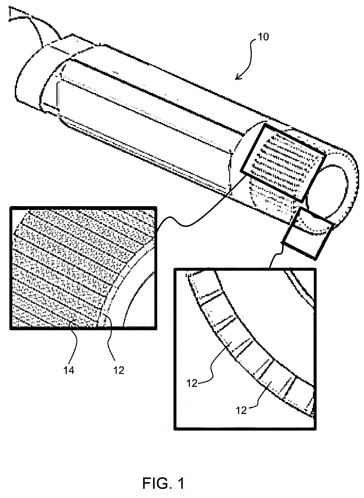
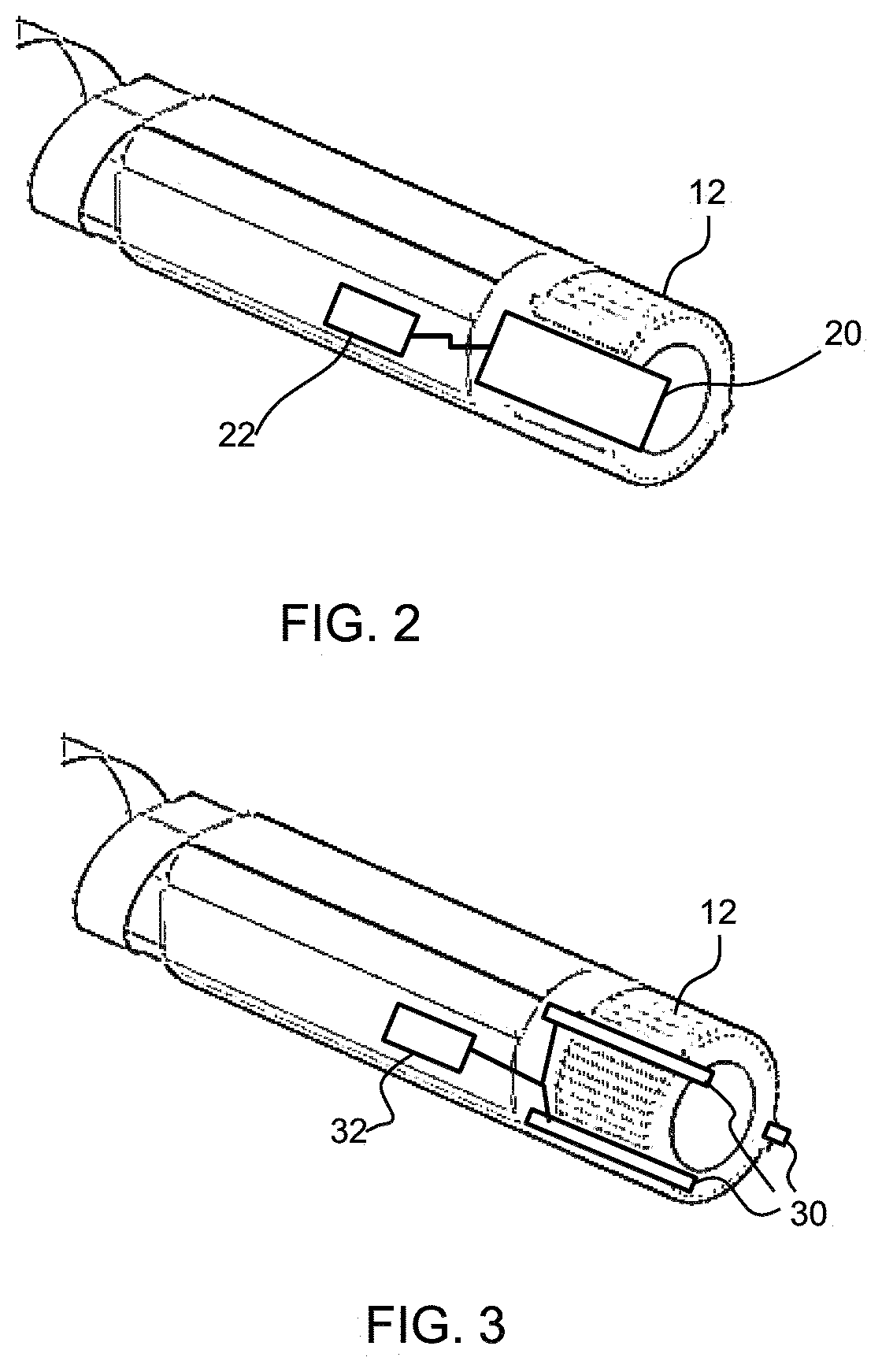
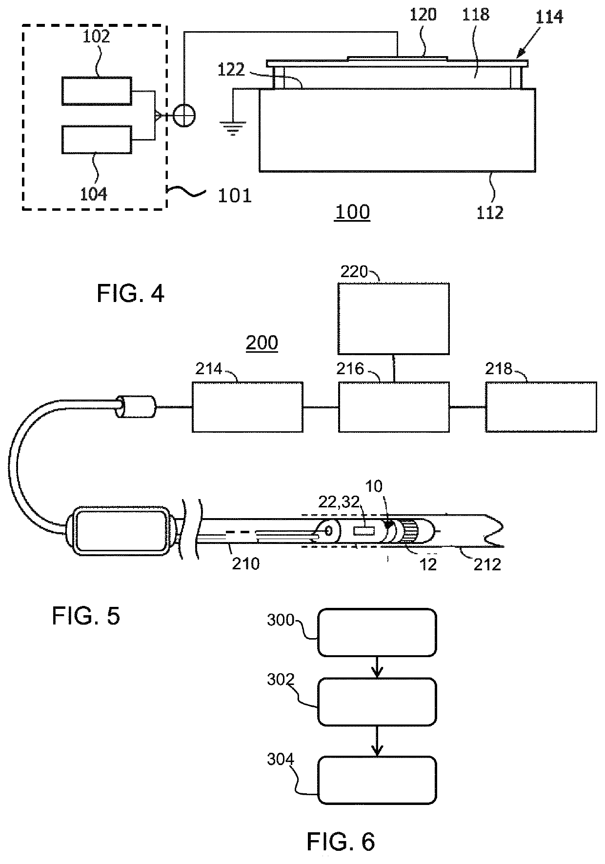
[0071]The invention provides an ultrasound imaging system, comprising an array of transducer elements. A first plurality of bias voltage circuits and a second plurality of transmit and receive circuits are provided, but they are used in a shared manner. To enable this, each bias voltage ci...


PUM


Abstract

The present invention relates to systems and methods that enable high frequency intraluminal imaging, such as IVUS or intra-cardiac echography (ICE), by reducing an amount of circuitry and wiring required to control the functions of one or more transducer array elements of an intraluminal device (e.g. catheter, guidewire, probe, etc.). In particular, aspects of the invention provide for selectively grouping transducers of an array that receive bias voltages from bias voltage circuitry and that are controlled by transmit and receive circuitry (also referred to as pulser/receiver circuitry). The selective grouping of the invention allows the same transmit and receive circuitry to stimulate one or more transducer elements to transmit signals while stimulating one or more other transducer elements to receive signals. Since a single transmit/receive circuit can, in accordance with the invention, drive transmit/receive functions of multiple transducer elements, less wiring is required to interconnect the transducer and the overall the size of imaging core can be reduced. As a result, systems and methods of the invention enable higher frequency imaging while maintaining a smaller device footprint capable of, e.g., traversing the lumens of the vasculature.

Description

FIELD OF THE INVENTION[0001]This invention relates to an ultrasound imaging system using an array of transducer elements, in particular capacitive micromachined ultrasound transducer (CMUT) elements.BACKGROUND OF THE INVENTION[0002]An array of transducer elements may be used when imaging is desired in a confined space.[0003]One key example is for intravascular ultrasound (IVUS) imaging. This is widely used in interventional cardiology as a diagnostic tool for a diseased vessel, such as an artery, within the human body to determine the need for treatment, to guide an intervention, and / or to assess its effectiveness. To perform an IVUS imaging study, an IVUS catheter that incorporates one or more ultrasound transducers is passed into the vessel and guided to the area to be imaged.[0004]The transducers emit and receive ultrasonic energy in order to create an image of the vessel of interest. Ultrasonic waves are partially reflected by discontinuities arising from tissue structures (such...

Claims


Application Information

Patent Timeline
Patent Type & Authority Applications(United States)
IPC IPC(8): A61B8/00A61B8/12A61B8/08A61B8/06
CPCA61B8/4488A61B8/12A61B8/5207A61B8/4494A61B8/06A61B8/5246A61B8/0883A61B8/0891A61B8/445A61B8/4461A61B8/54
Inventor VAN RENS, ANTONIA CORNELIA
Owner KONINKLIJKE PHILIPS ELECTRONICS NV
Why Eureka
Try Eureka