
Pressing structure

a technology of pressing structure and pressing plate, which is applied in the direction of presses, metal-working apparatuses, contacts, etc., can solve problems such as deformation or damage, and achieve the effects of preventing deformation and damage of electronic components, and reducing excessive pressure for

Active Publication Date: 2021-02-18
CHENG UEI PRECISION IND CO LTD
View PDF0 Cites 0 Cited by
  • Summary
  • Abstract
  • Description
  • Claims
  • Application Information

AI Technical Summary

Benefits of technology

The patent text describes a structure that uses cushion elements to reduce the pressure force on a rocker component when it is pressed onto an electronic component. This prevents damage or deformation to the electronic component. The technical effect of this structure is to provide a safe and reliable method for mounting components onto electronic devices.

Problems solved by technology

At the time of proceeding with the manufactured pressure operation, the pressing structure proceeds with a downward pressure, the downward pressure frequently exceeds a strength capable of being loaded by the more elaborated electronic components, so that each electronic component easily suffers an excessive pressure to cause a deformation or a damage.

Method used


Image

  • Pressing structure
  • Pressing structure
  • Pressing structure

Examples


Embodiment Construction

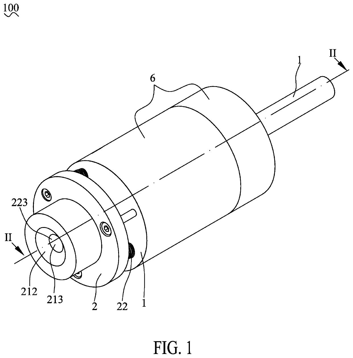
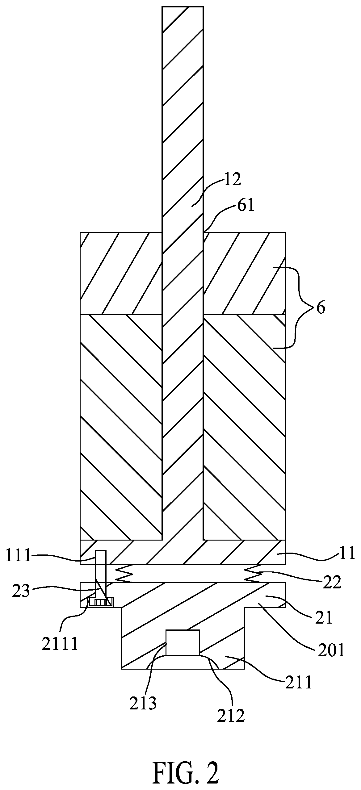
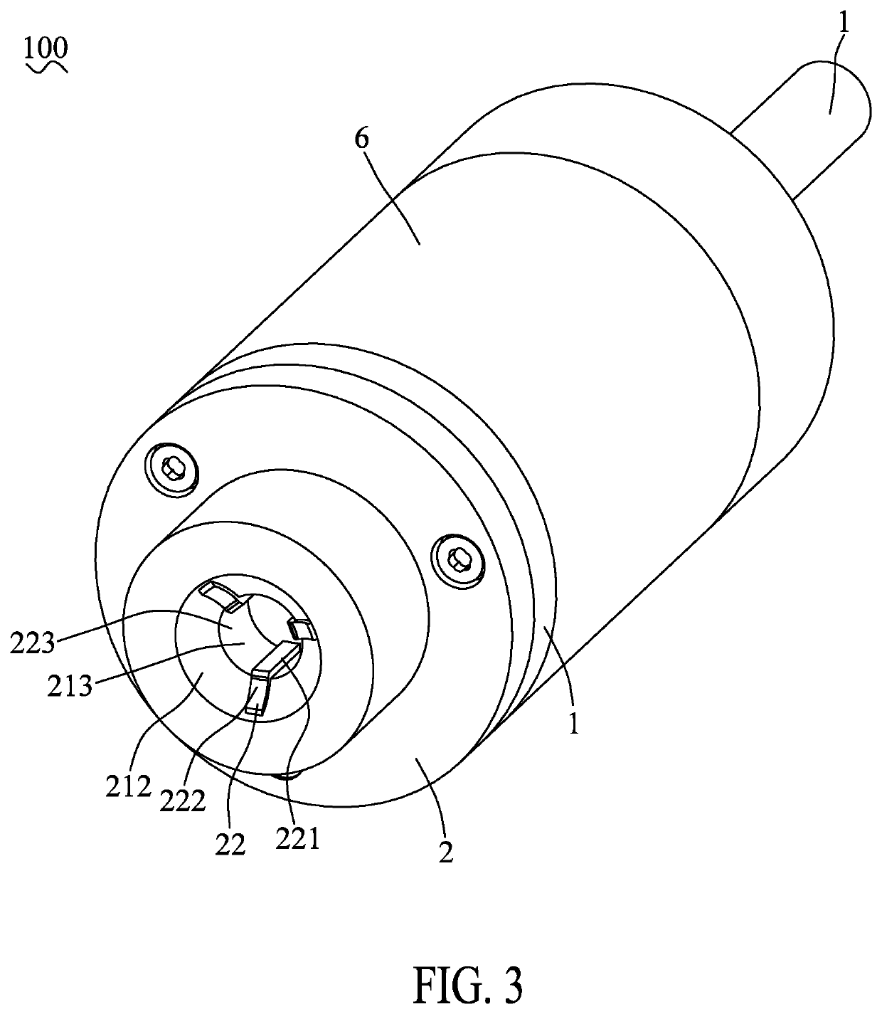
[0019]With reference to FIG. 1, FIG. 2 and FIG. 4, a pressing structure 100 in accordance with a first preferred embodiment of the present invention is shown. The pressing structure 100 is adapted for mounting a rocker component 200 on an electronic component 300. The pressing structure 100 includes a support frame 1 and a pressing element 2.

[0020]The support frame 1 has a base plate 11, and a pole stander 12 protruded upward from a middle of a top surface of the base plate 11. Several portions of a bottom surface of the base plate 11 are recessed inward to form a plurality of first fixing holes 111.

[0021]The pressing element 2 is mounted under the support frame 1. The pressing element 2 is mounted to the bottom surface of the base plate 11. The pressing element 2 includes a pedestal 21 and a cushion element 22. Preferably, the pressing element 2 includes a plurality of cushion elements 22. The pedestal 21 has a rectangular base board 201. A middle of a bottom surface of the base bo...


PUM


Abstract

A pressing structure includes a support frame and a pressing element. The pressing element is mounted to a bottom surface of the base plate. The pressing element includes a pedestal and a cushion element. The pedestal has a base board. A bottom surface of the base board protrudes downward to form a pressing block. A bottom surface of the pressing block is recessed upward and gradually arched outward from top to bottom to form a first pressing face. The rocker component has a base portion. The first pressing face is in contact with the base portion. The cushion element is mounted on the pedestal, so that the rocker component is mounted on the electronic component by the pressing structure, the rocker component and the electronic component are without affording the excessive pressure force to cause a damage and a deformation of the electronic component.

Description

CROSS-REFERENCE TO RELATED APPLICATION[0001]The present application is based on, and claims priority form, China Patent Application No. 201921322241.2, filed Aug. 15, 2019, the disclosure of which is hereby incorporated by reference herein in its entirety.BACKGROUND OF THE INVENTION1. Field of the Invention[0002]The present invention generally relates to a pressing structure, and more particularly to a pressing structure capable of absorbing an excessive pressure force which is caused by the pressing structure exerted on a processed component during a pressure operation.2. The Related Art[0003]In a process of assembling products, in order to avoid accumulated tolerances in assembly, a pressing machine is often used to eliminate accumulated tolerances of a pressing assembly. Whereas a conventional pressing structure proceeds with a manufactured pressure operation in the pressing machine, pneumatic cylinders are used to push the pressing structure downwards for proceeding with the man...

Claims


Application Information

Patent Timeline
Patent Type & Authority Applications(United States)
IPC IPC(8): B23P19/02H01H11/00
CPCB23P19/02H01H11/00H01H25/04H01H1/5805B30B15/068
Inventor LEE, TSUNG SHIHTSENG, CHI MINGCHENG, CHIA FA
Owner CHENG UEI PRECISION IND CO LTD
Learn More