
Body part element comprising a heating film

Pending Publication Date: 2021-02-04
CO PLASTIC OMNIUM
View PDF3 Cites 2 Cited by
  • Summary
  • Abstract
  • Description
  • Claims
  • Application Information

AI Technical Summary

Benefits of technology

The invention provides a method for making a more robust and aesthetic element to be mounted on a bodywork part, specifically a radome. The method involves adding one or more heating tracks to areas that require heat contribution to improve defrosting efficiency. The support element is separated from the molded layer only by the heating tracks, reducing space requirements and increasing strength of the final part. The method also includes applying a coating to the support element to improve resistance to UV rays or scratching. The support sheet is fixed to the film to hold it during the overmolding step and can be made from a variety of materials. The heating tracks are arranged independently for better distribution and esthetic appearance. Overall, the invention provides a faster, stronger, and more efficient solution for mounting elements on bodywork parts.

Problems solved by technology

The normal operation of some sensors, such as the one cited in the example above, can be disrupted by the presence of a layer of ice, snow or frost in the event of temperatures below 10 degrees Celsius.
This layer of frost disrupts the normal passage of electromagnetic waves, which is a source of error for the evaluation of external physical parameters.
Thus, the two layers of plastic are separated from one another by the film, which has a large bulk, making the radome not very robust and not very waterproof.

Method used


Image

  • Body part element comprising a heating film
  • Body part element comprising a heating film

Examples


first embodiment

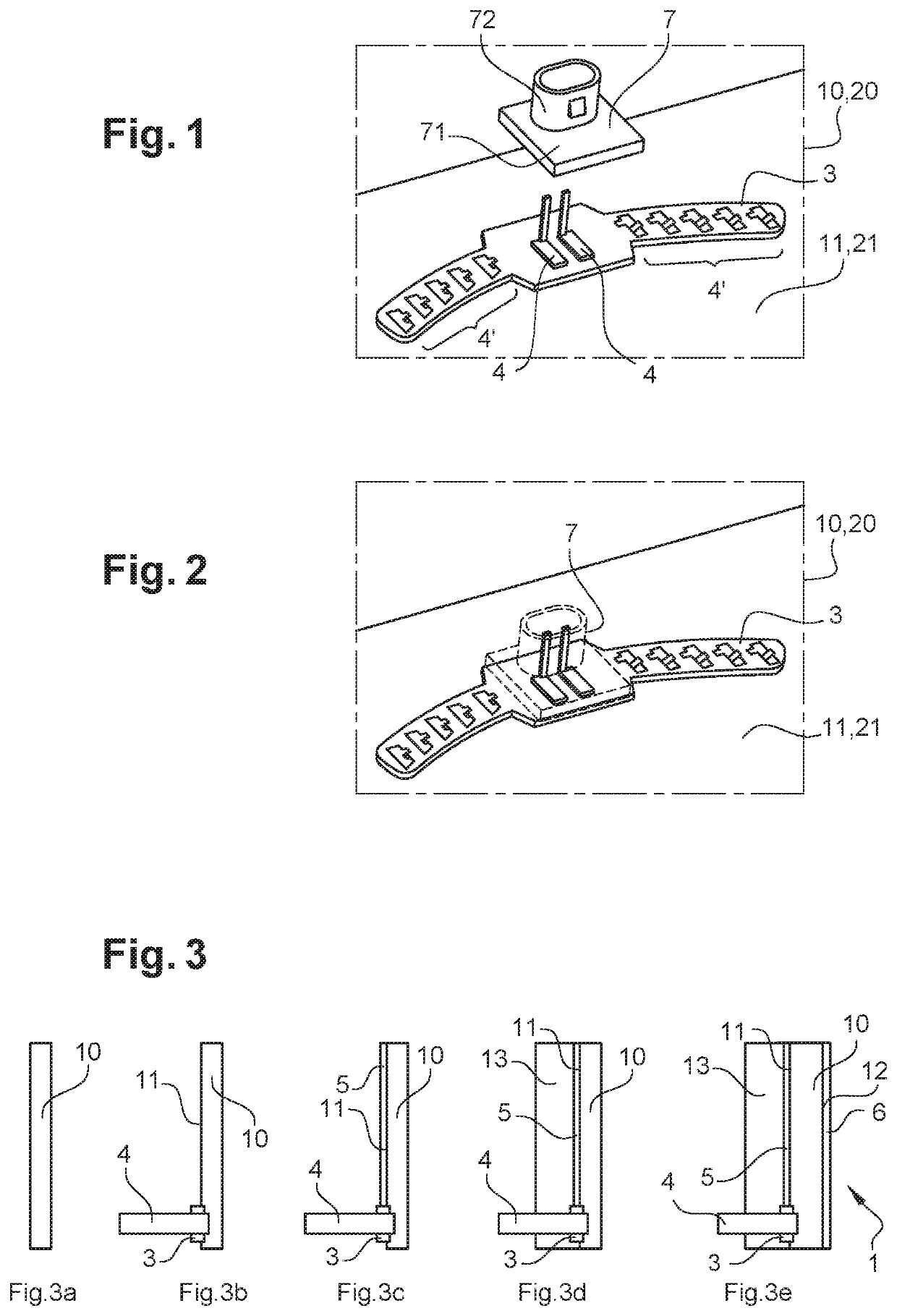
[0045]Now, we will describe the first embodiment, which is visible in FIGS. 3a-3e. According to this embodiment, the support element 10 is a plastic film as illustrated in FIG. 3a. This film can be produced by extrusion or calendering before fixing a support sheet 3 comprising at least one connection member 4 on a first face 11 of the film as illustrated in FIG. 3b. It is also conceivable to use a commercially available film. The film forms a first transparent layer.

[0046]As can be seen in FIG. 3c, a heating track 5 is placed on the film, the heating track 5 being arranged on the first face 11 of the support element 10. Then, the heating track 5 is connected to the connection member 4, for example by soldering. The heating track 5 is distributed homogeneously over the entire surface of the film and is fixed thereto by gluing or by local melting of the film.

[0047]A molding step is then carried out in which the support element 10 is arranged in a molding chamber of a mold defining the...

second embodiment

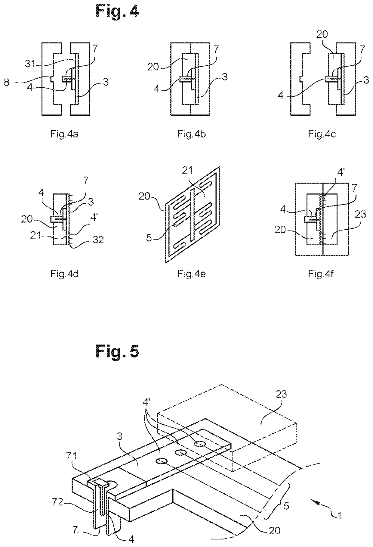
[0048]In order to improve the resistance of the element to UV rays and to protect it from scratching, it is possible to deposit a coating 6 on a second face 12 of the film that is opposite the first face 11 as shown in FIG. 3e. This step can also be considered in the second embodiment, which is illustrated in FIGS. 4 and 5.

[0049]According to the second embodiment of the present invention, the support element 20 is a molded part forming a first transparent layer that is obtained by the following steps: a support sheet 3 comprising at least one connection member 4 is placed in a molding chamber of a mold defining the shape of the molded part as shown in FIG. 4a. A first face 31 of the support sheet 3 is placed facing the inside of the molding chamber. When the mold is closed, a plastic material, for example a thermoplastic material, is injected into the molding chamber as shown in FIG. 4b and the molded part covering the first face 31 of the support sheet 3 is obtained as shown in FIG...


PUM

PropertyMeasurementUnit
Shapeaaaaaaaaaa
Transparencyaaaaaaaaaa

Abstract

A method for manufacturing an element for a bodywork part successively including the steps of producing a support element having a first face on which a support sheet is fixed having at least one connection member, arranging a heating track on the support element, the heating track being arranged on the first face of the support element, connecting the heating track to the connection member, and arranging the support element in a molding chamber of a mold defining the shape of the element for a bodywork part, the first face of the support element facing the inside of the molding chamber, and injecting a plastic material into the molding chamber in order to cover the heating track.

Description

FIELD OF THE INVENTION[0001]The invention relates to the field of motor vehicles. And more particularly the field of the manufacture of a plastic element, intended to be mounted on a bodywork part.BACKGROUND OF THE INVENTION[0002]Many modern vehicles are fitted with plastic bodywork components which can be fitted, for example, to a rear hatch, a door blank, front and rear bumpers, a roof, etc.[0003]In particular, since the introduction of driving assistance systems, there has been a need to place sensors of various kinds on certain plastic bodywork parts, in order to measure external physical parameters representative of the external environment of the motor vehicle. All of the values of these parameters form information available in real time on the environment of the vehicle.[0004]Bodywork elements are then used, attached to the bodywork part, for example having a radome function, that is to say an element transparent to electromagnetic waves protecting and hiding sensors. In a co...

Claims


Application Information

Patent Timeline
IPC IPC(8): H05B1/02B29C45/14B32B27/40B32B15/08
CPCH05B1/0236B29C45/14639B29C45/14819B29L2031/3044B32B15/08B29C2045/14868B32B27/40H01Q1/422H01Q1/3208H01Q1/3233H01Q1/02B29C45/14811B29C2045/14844B29C45/14836B29K2995/0026B29K2995/0029H05B2214/02H05B2203/013H05B3/286H01Q1/3275H01Q1/3283H01Q1/425B29K2075/00B32B2307/412B32B2605/00B29K2995/0005
Inventor DUBOST, ELISESTABLO, FRÉDÉRICTRESSE, DAVIDBOISSON, DAMIENJACQUEMET, THIERRYSELMANE, ISMAEL
Owner CO PLASTIC OMNIUM
Learn More