Aircraft wheel and brake assembly
a technology for aircraft and brakes, applied in aircraft braking arrangements, aircraft components testing, brake safety systems, etc., can solve the problems of reducing the cost and mass of a system, reducing the risk of damage to electrical equipment, electrical wires and connectors, and reducing the risk of damag
- Summary
- Abstract
- Description
- Claims
- Application Information
AI Technical Summary
Benefits of technology
Problems solved by technology
Method used
Image

Examples
first embodiment
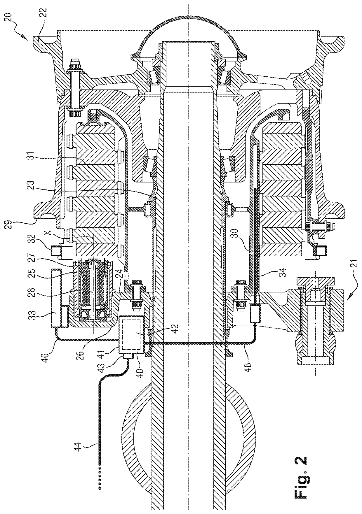
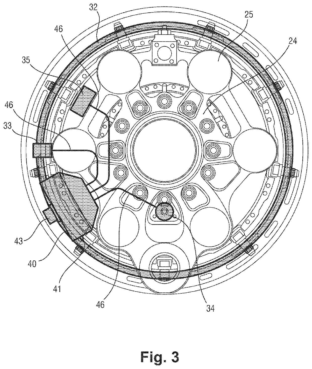
[0050]An aircraft wheel and brake assembly according to the invention when it is assembled is described below with reference to FIGS. 2 and 3.
[0051]The aircraft wheel and brake assembly firstly includes a wheel 20 of an aircraft landing gear and a brake 21 for braking the wheel 20.
[0052]The wheel 20 includes a rim 22 that receives a tyre and is mounted rotatably on an axle 23 located at the bottom of the landing gear.
[0053]Here, the brake 21 is a hydraulic brake. The brake 21 comprises an actuator bracket, in this case a brake ring 24, that holds at least one brake actuator, in this case a plurality of brake actuators 25. The brake ring 24 is mounted on the axle 23.
[0054]The brake ring 24 comprises a plurality of casings 26 with a generally cylindrical outer shape. Each casing 26 defines a cavity that opens onto the side of the wheel 20 and forms a piston housing.
[0055]Each brake actuator 25 comprises a cylindrical sleeve 27 in which a piston 28 is mounted, arranged to slide along a...
second embodiment
[0107]With reference to FIG. 9, in a wheel and brake assembly the first sensing component 60 of the first measuring device, i.e. here, the Hall effect sensor 60 that produces a measurement signal representing the rotation speed of the wheel, is incorporated into or on the data concentrator 61. Similarly, the second sensing component 62 of the third measuring device, i.e. here the LVDT that produces a measurement signal representing the wear of the stack of discs, is incorporated into or on the data concentrator 61.
[0108]The data concentrator 61 becomes a one-piece member that includes the wheel speed sensor, the brake wear sensor and the brake temperature sensor packaging. This solution is more compact and reduces the number of electrical wires on the brake.
third embodiment
[0109]With reference to FIG. 10, in a wheel and brake assembly the first sensing component 70 and the first target 71 of the first measuring device are installed in different locations.
[0110]The first sensing component 70, which again is a Hall effect sensor 70, is installed on the torque tube 72 of the brake and, more particularly, inside the torque tube 72, on a transverse annular web 73 of the torque tube 72.
[0111]The first target 71 is again a toothed wheel and is mounted on the hub 74 of the wheel. Alternatively, the hub 74 could be manufactured so that it has protrusions, for example alternating teeth and recesses, so that the hub 74 forms the first target 71.
[0112]The third embodiment makes it possible to improve the control of the clearance between the first sensing component 70 and the first target 71 and the relative positions of the first sensing component 70 and the first target 71. The mass of the first measuring device is reduced. However, the first measuring device i...
PUM
 Abstract
Description
Claims
Application Information
 - R&D
- Intellectual Property
- Life Sciences
- Materials
- Tech Scout
- Unparalleled Data Quality
- Higher Quality Content
- 60% Fewer Hallucinations
Browse by: Latest US Patents, China's latest patents, Technical Efficacy Thesaurus, Application Domain, Technology Topic, Popular Technical Reports.
© 2025 PatSnap. All rights reserved.Legal|Privacy policy|Modern Slavery Act Transparency Statement|Sitemap|About US| Contact US: help@patsnap.com