
Servo controller

a servo controller and controller technology, applied in the field of servo controllers, can solve the problems of difficult to reduce the cycle time, vibration is likely to occur, scratching may be produced on the surface of the machining, etc., to enhance the yield, enhance the accuracy of machining of the machine tool, and enhance the accuracy of the operation of the industrial machine.

Active Publication Date: 2021-01-21
FANUC LTD
View PDF0 Cites 0 Cited by
  • Summary
  • Abstract
  • Description
  • Claims
  • Application Information

AI Technical Summary

Benefits of technology

The patent describes a servo controller that can adjust its parameters based on the machine's position and inertia during operation. By doing so, it can optimize its performance and make it faster and more accurate. This improves the efficiency of the machine and reduces vibration, resulting in better quality machining. Overall, the servo controller helps to make machines function better and faster.

Problems solved by technology

In this way, it is difficult to reduce a cycle time.
Alternatively, in a case where parameters are set so as to be optimal under certain conditions, when inertia and a position are changed, the parameters are not optimal, and thus vibration is likely to occur at the time of machining in a machine tool, with the result that, for example, a scratch may be produced in the surface of the machining.
Of the methods described above, in the method of adaptively changing parameters, it is necessary to estimate the state and calculate optimal values in real time, and thus problems are present in which (A) a calculation load is increased (=an expensive computation device is needed), in which (B) since estimation calculation uses FB data obtained in real time from sensors, an influence of noise is received and in which (C) it is difficult adjust hyper parameters used for the estimation calculation itself.
In (2) the case of changing parameters systematically in advance, only information within a CNC (numerical controller) is often not sufficient enough to produce an optimal parameter schedule.

Method used


Image

  • Servo controller
  • Servo controller
  • Servo controller

Examples


Embodiment Construction

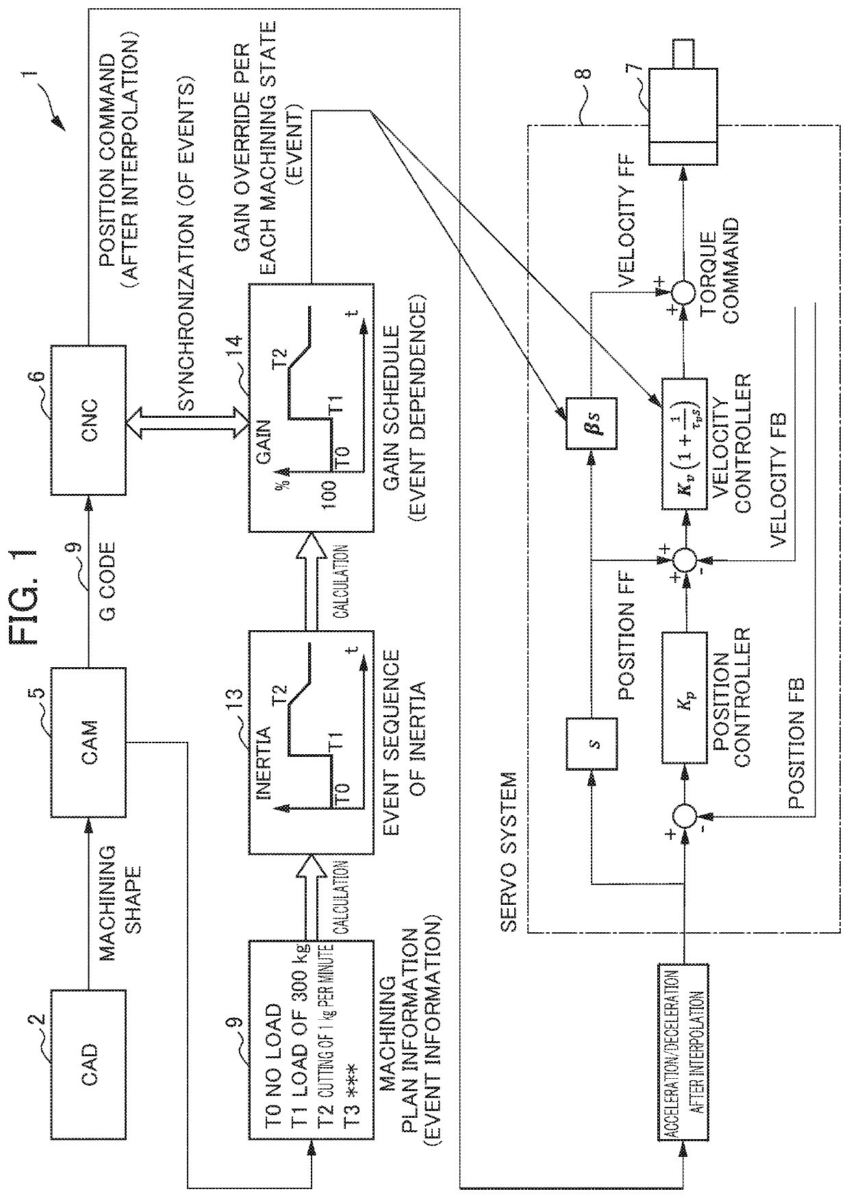
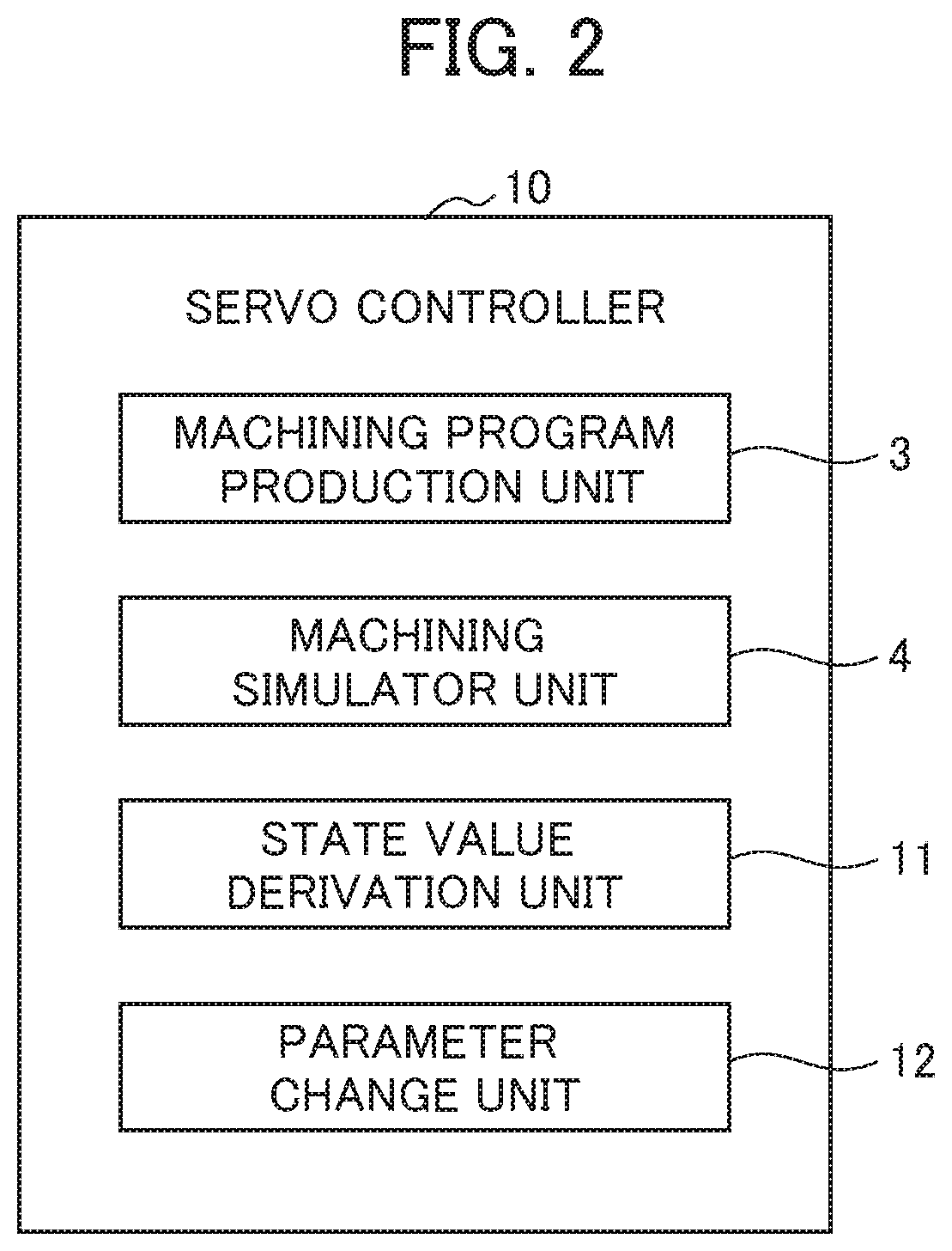
[0023]A servo controller according to an embodiment will be described below with reference to FIGS. 1 to 7.

[0024]In the present embodiment, a description will first be given with the assumption that an industrial machine is a machine tool and that an electric motor is a servo motor which drives the spindle (axis, driven member) or the like of the machine tool. However, the industrial machine according to the present invention may be naturally another industrial machine such as a robot, a transport device, a measurement device, a test device, a press machine, a press-fitting device, a printing machine, a die casting machine, an injection molding machine, a food machine, a packaging machine, a welding machine, a washing machine, a coating machine, an assembly device, a mounter, a woodworking machine, a sealing device or a cutting machine.

[0025]As shown in FIGS. 1 and 2, the control system 1 of the machine tool of the present embodiment first includes: a CAD 2 for performing design, dr...


PUM


Abstract

An object is to provide a servo controller which constantly optimizes parameters according to the state of a machine. A servo controller for controlling an electric motor which drives the axis of an industrial machine includes: a state value derivation unit which derives, from an operation program and / or operation plan information of the industrial machine, the chronological or event-sequential data of the state value of the electric motor or a driven member that is operated with the electric motor; and a parameter change unit which changes at least one parameter of a velocity gain, a position gain, a feedforward gain, a filter frequency and an acceleration / deceleration time constant after interpolation based on the chronological or event-sequential data derived in the state value derivation unit either chronologically or event-sequentially.

Description

[0001]This application is based on and claims the benefit of priority from Japanese Patent Application No. 2019-133481, filed on 19 Jul. 2019, the content of which is incorporated herein by reference.BACKGROUND OF THE INVENTIONField of the Invention[0002]The present invention relates to servo controllers.Related Art[0003]As is known, in the field of machine work, CNC (Computerized Numerical Control) technology is applied, the amount of movement, the velocity of the movement and the like are numerically controlled with a computer and thus the repetition of the same operation, a complicated operation and the like are highly automated.[0004]Design and drafting are performed with a CAD (Computer Aided Design), an operation program (such as a machining program) corresponding to CAD data is produced with a CAM (Computer Aided Manufacturing), data produced with the CAM is taken into a CNC, for example, various types of data such as options, parameters, an NC program, a macro program, a mac...

Claims


Application Information

Patent Timeline
Patent Type & Authority Applications(United States)
IPC IPC(8): G05B19/4155
CPCG05B19/4155G05B2219/34013G05B19/4097H02P29/00H02P29/20G05B19/40938G05B2219/41435G05B2219/49065G05B2219/36103Y02P90/02G05B19/404G05B19/41G05B19/4103G05B19/416
Inventor SHIMODA, TAKAKIIKAI, SATOSHI
Owner FANUC LTD
Learn More