
Efficient interconnecting layer for tandem solar cells

a tandem solar cell and interconnection layer technology, applied in the field of solar cell construction, can solve the problems of difficult to achieve greater than 10% power conversion efficiency (pce) from single junction based pscs, low cost, and high-throughput production of pscs requires the development of a technology that is unlimited, and achieves the effects of reducing optical losses, reducing production costs, and selective collection of charge carriers

Active Publication Date: 2021-01-14
THE UNITED STATES OF AMERICA AS REPRESETNED BY THE SEC OF THE AIR FORCE
View PDF0 Cites 0 Cited by
  • Summary
  • Abstract
  • Description
  • Claims
  • Application Information

AI Technical Summary

Benefits of technology

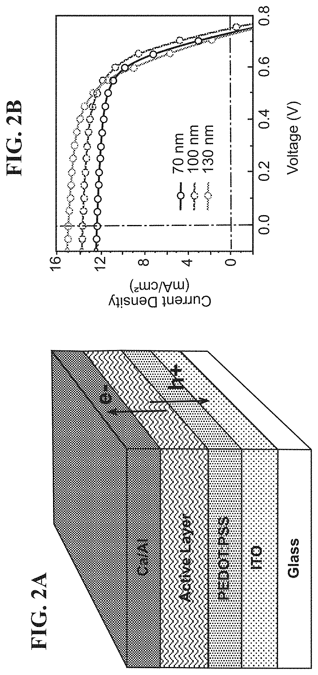
[0017]According to another embodiment of the invention, the layer of P(T3-il)-2:PC71BM is about 70-130 nm thick, e.g. about 100 nm thick. This embodiment provides the advantage of an active layer that is optimized with regard to form factor (FF), short-circuit current density (JSC), and open circuit voltage (VOC) considerations.
[0018]According to another embodiment of the invention, the tandem solar cell further comprises applying a top electrode of Ca / Al over the P(T3-il)-2:PC71BM layer. The layer of calcium (Ca) may be about 2 nm thick, and the layer of aluminum (Al) on top of the Ca layer may be about 100 nm thick. This embodiment provides the advantage of selective collection of charge carriers i.e. electrons at the top electrode.
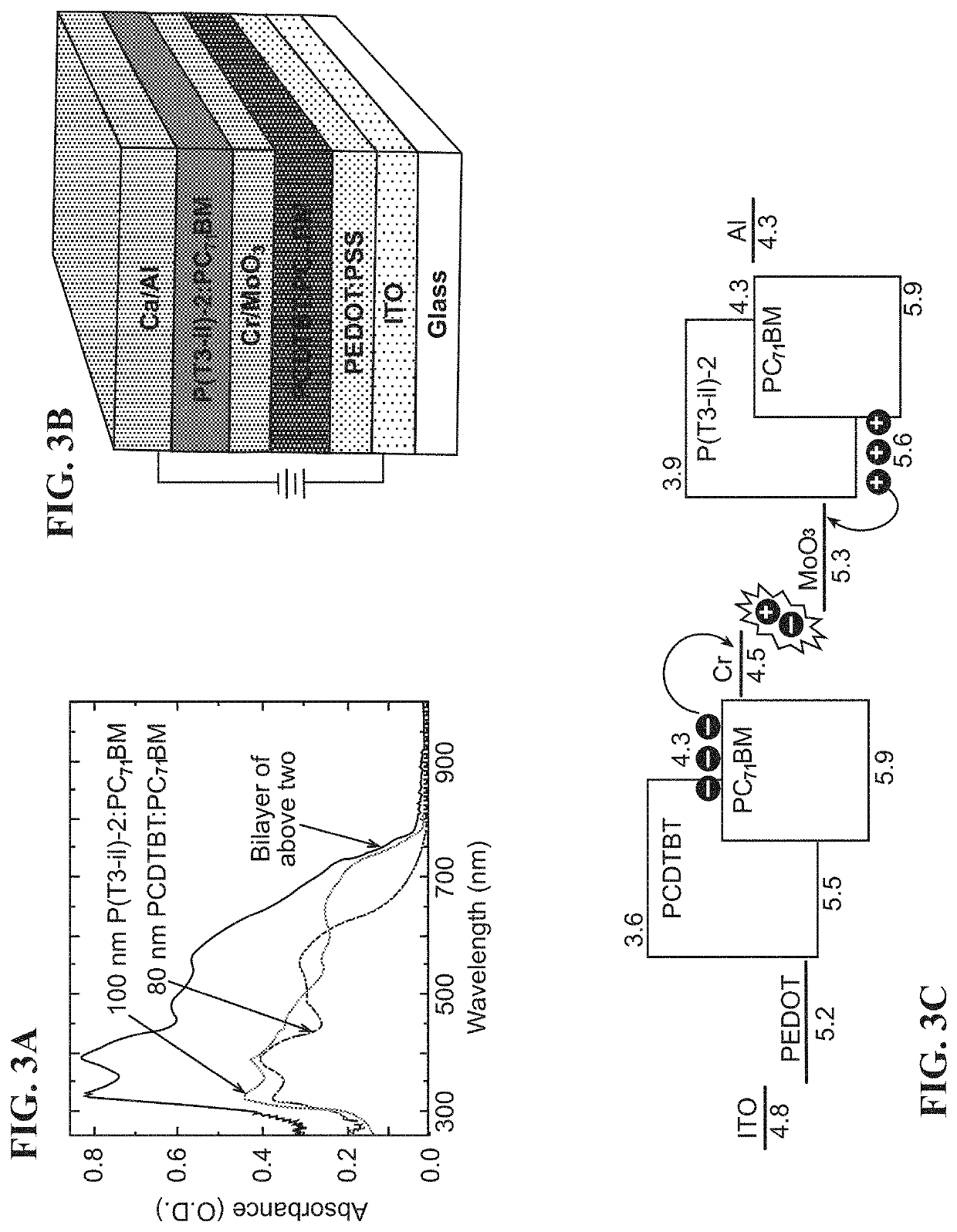
[0019]According to a further embodiment of the invention, a tandem solar cell comprising a front subcell; a back subcell; and an interconnecting layer of Cr / MoO3 between the back subcell and the front subcell and connecting the two subcells in series. This embodiment provides the advantage of an interconnecting layer that allows the electrons from the front subcell, e.g. PCDTBT:PC71BM, to combine with the holes from the back subcell, e.g. P(T3-il)-2:PC71BM at the Cr / MoO3 interface, and the Cr / MoO3 interface is chemically inert with regard to those chemicals utilized in the manufacture of the solar cells so that the other layers of the solar cell are not damaged, and the interconnecting layer is over 80% transparent to light in the range of 400-1000 nm, minimizing optical losses.
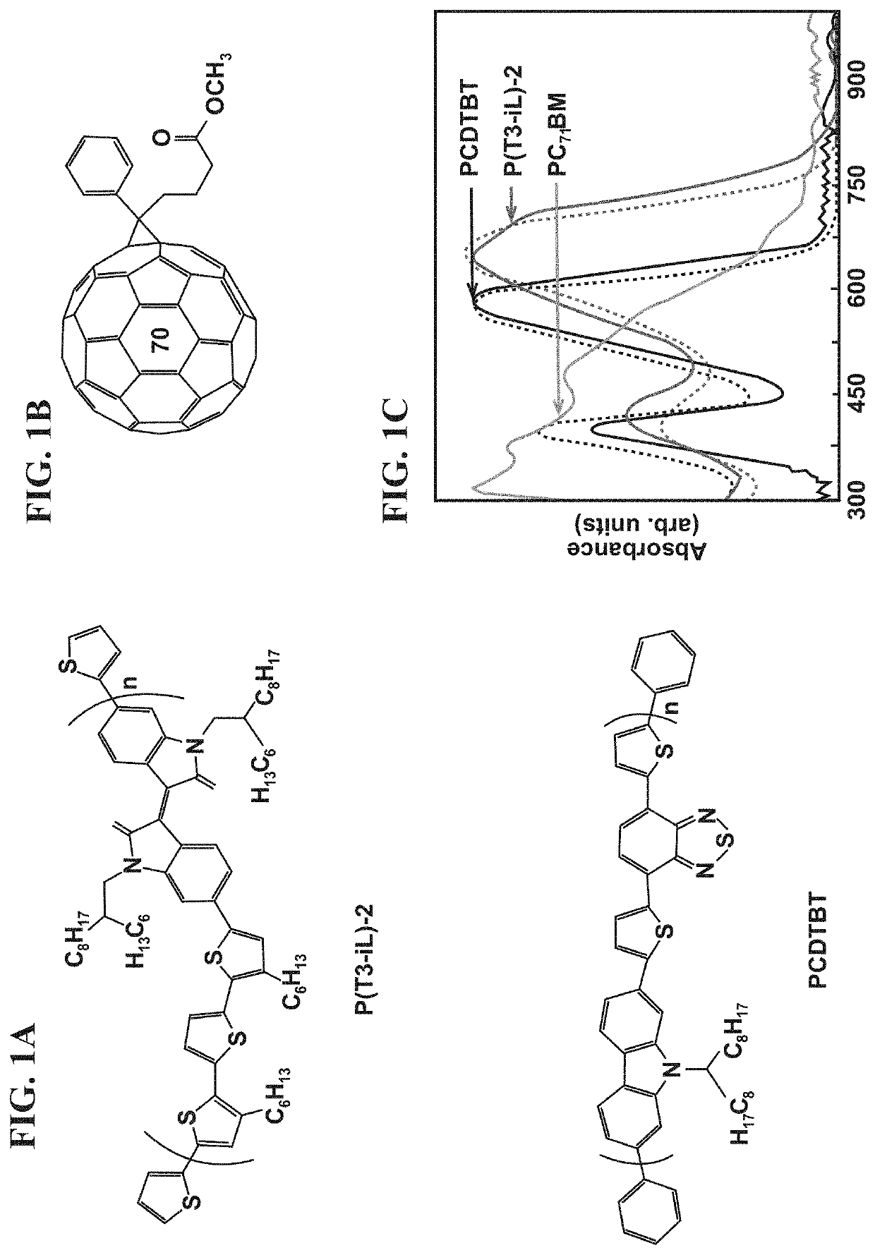
[0020]According to another embodiment of the invention, the front subcell comprises a carbazole-thienyl-benzothiadiazole based polymer. This embodiment provides the advantage of higher adsorption of high energy photons.
[0021]According to a further embodiment of the invention, the back subcell comprises an isoindigo-based polymer. This embodiment provides the advantage of simple, high yield and scalable synthetic routes for the isoindigo compounds, as well as the natural occurrence of their fundamental building units. Isoindigo-based polymers may enable low-cost, high-throughput PSC production capability due to their high yield synthesis, scalability, and low band-gap properties. This embodiment also adds the advantage of higher adsorption of low energy photons.
[0022]According to another embodiment of the invention, the front subcell comprises a carbazole-thienyl-benzothiadiazole based polymer and the back subcell comprises an isoindigo-based polymer. This embodiment provides the advantage of a broader range of photon capture in the solar spectrum.

Problems solved by technology

However, the inherent material properties of the conjugated polymers, such as low charge carrier mobility and lack of a broad absorption in the solar spectrum with proper charge-transport properties, constitute a bottleneck to their continued development and it is quite challenging to achieve greater than 10% power conversion efficiency (PCE) from single junction based PSCs.
Additionally, the low cost, solution-processed, high-throughput production of PSCs requires the development of a technology that is unlimited by materials supply.
It is difficult to satisfy all of these desired properties with a single material.
A major challenge faced during the integration of ILs with solution processed photoactive components is the difficulty in controlling the process such that the underlying layers are not destroyed upon further processing.

Method used


Image

  • Efficient interconnecting layer for tandem solar cells
  • Efficient interconnecting layer for tandem solar cells
  • Efficient interconnecting layer for tandem solar cells

Examples


examples

[0045]Single Junction Device Fabrication. All solar cell devices were fabricated on patterned ITO glass (Sheet resistance of 15Ω / □). On the day of deposition, the ITO glass substrates were cleaned sequentially by sonicating with detergent, deionized water, acetone, and iso-propanol, followed by drying with high flow of nitrogen and UV-ozone treatment for 20 min. Filtered (0.45 micron PVDF filter) poly-(3,4-ethylenedioxythiophene:poly(styrenesulfonic acid) (PEDOT:PSS; Clevios Al4083 from Heraeus Materials Technology) was spin-coated on clean ITO glass substrates at 3000 rpm for 60 s and then dried on a ceramic hot-plate at 160° C. for 20 min in air. Thereafter, substrates were immediately taken to a nitrogen-filled glove box for active layer deposition. For single junction PCDTBT device of different thickness, PCDTBT:PC71BM (1:2 weight ratio; 2 volume% of DIO as processing additive) blend in chloroform was spin-coated on top of ˜40 nm PEDOT:PSS at 2000 rpm for 60 s in the concentrati...


PUM

PropertyMeasurementUnit
molecular weightaaaaaaaaaa
thickaaaaaaaaaa
thickaaaaaaaaaa

Abstract

A tandem solar cell comprises a front subcell; a back subcell; and an interconnecting layer of Cr/MoO3 between the front subcell and the back subcell and connecting the two subcells in series. The back subcell may be an isoindigo-based polymer. The front subcell may comprise a carbazole-thienyl-benzothiadiazole based polymer. The front subcell may comprise an isoindigo-based polymer. The isoindigo-based polymer is a repeating 2-thiophene-terminated polymer. A tandem solar cell comprises a substrate layer; a layer of PCDTBT:PC71BM applied on the substrate layer; a bilayer of chromium and MoO3 applied to the PCDTBT:PC71BM layer; a layer of P(T3-il)-2:PC71BM applied on the bilayer of chromium and MoO3; and Ca and Al electrode layer on the top.

Description

PRIORITY[0001]Pursuant to 37 C.F.R. § 1.78(a)(4), this application claims the benefit of and priority to prior filed co-pending Provisional Application Ser. No. 62 / 437,289, filed Dec. 21, 2016, and Non-Provisional application Ser. No. 15 / 719,617, filed Sep. 29, 2017, which are expressly incorporated herein by reference.RIGHTS OF THE GOVERNMENT[0002]The invention described herein may be manufactured and used by or for the Government of the United States for all governmental purposes without the payment of any royalty.FIELD OF THE INVENTION[0003]The present invention relates generally to solar cell construction and, more particularly, to an efficient interconnecting layer for tandem solar cells.BACKGROUND OF THE INVENTION[0004]Solution-processed polymer solar cells (PSCs) are some of the most actively studied devices amongst the photovoltaic (PV) community due to their potential for fabricating lightweight and large-area flexible PV devices by low-cost, roll-to-roll compatible deposit...

Claims


Application Information

Patent Timeline
Patent Type & Authority Applications(United States)
IPC IPC(8): H01L27/30H01L51/00H01L51/42H01L51/44
CPCH01L27/302H01L51/0035H01L51/4253H01L51/442H01L51/0047H01L51/0021H01L51/0003H01L51/0036H01L51/0043Y02E10/549Y02P70/50H10K85/113H10K85/111H10K85/215H10K30/30H10K30/57H10K30/82H10K71/12H10K71/60H10K85/151
Inventor BAG, SANTANUPATEL, ROMESH J.DURSTOCK, MICHAEL F.LEEVER, BENJAMIN J.
Owner THE UNITED STATES OF AMERICA AS REPRESETNED BY THE SEC OF THE AIR FORCE
Learn More