
Method for adaptive functional reconfiguration of operating elements of an image acquisition system and corresponding image acquisition system

a technology of image acquisition system and operating element, applied in the field of image acquisition method, can solve the problems of complex and tedious operation of camera head, inability to fully utilize the system's technical options, and inability to adjust the necessary image acquisition parameters, etc., to achieve simplified operation of image acquisition system, facilitate control and/or adjustment, and greatly simplify the effect of working with the endoscopy system

Pending Publication Date: 2021-01-14
SCHOLLY FIBEROPTIC
View PDF5 Cites 1 Cited by
  • Summary
  • Abstract
  • Description
  • Claims
  • Application Information

AI Technical Summary

Benefits of technology

The image acquisition system described in this patent offers a user-friendly way to control and adjust the functions of the system. This is because the system is intelligent and can adjust these functions based on the user's needs. This makes it easier for the user to operate the system and get the desired results. The system can also adjust the functions of external devices that work with the system. Overall, this simplifies the process of operating the image acquisition system and makes it more user-friendly and efficient.

Problems solved by technology

Users of such image acquisition systems, particularly such endoscopy systems, are often not capable of fully utilizing the technical options of the systems.
A commonplace reason for this is often that the operation, particularly the adjustment of necessary image acquisition parameters, is complicated and tedious.
With previously known endoscopy systems, the reason for this is that specifically the operation of the camera head, which reads out and controls the image sensor of the endoscope, and / or of the entire video endoscope is often hardly intuitive and frequently very complex, particularly when the endoscopy system is overloaded with functions.

Method used


Image

  • Method for adaptive functional reconfiguration of operating elements of an image acquisition system and corresponding image acquisition system
  • Method for adaptive functional reconfiguration of operating elements of an image acquisition system and corresponding image acquisition system

Examples


Embodiment Construction

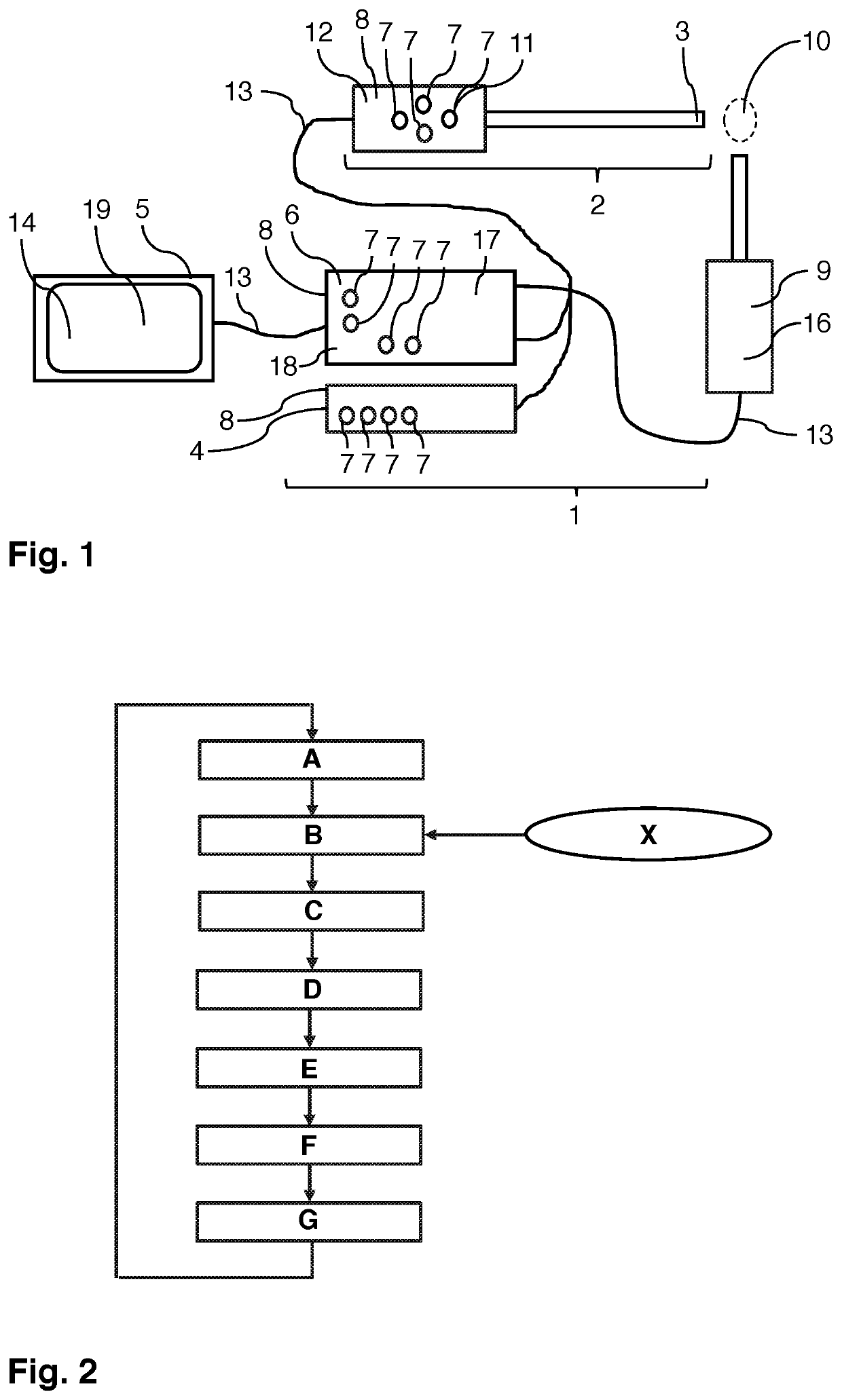
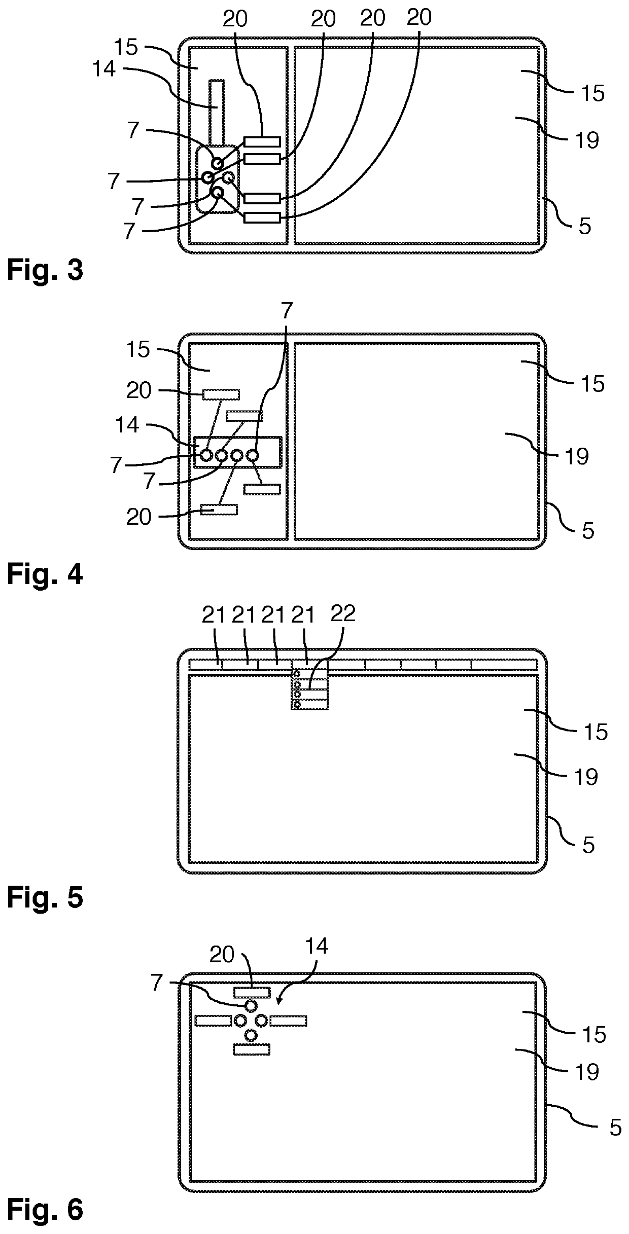
[0092]FIG. 1 shows an image acquisition system 1 according to the invention in the form of an endoscopy system which comprises several components 8, namely: An endoscope 2 with a camera head 12, which reads out an image sensor 3 of the endoscope 2 and on which operating elements 7 are formed in the form of several keys and rotary knobs, i.e. mechanical manipulators 11; a corresponding camera control unit 6 for processing an image sequence recorded with the image sensor 3 in the form of a video image data stream; as well as a light source 4 for illuminating a region of interest (ROI), i.e. the particular object region which is of interest and being examined with the endoscope 2, as is illustrated in FIG. 1. To this end, the light source 4 is connected to the endoscope 2 by means of fiber optics.

[0093]As can further be seen in FIG. 1, the endoscopy system 1 is connected to a display unit 5, in the form of an external monitor, via a cable and connected to an external device 9, in the f...


PUM


Abstract

In summary, to simplify operation of a medical image acquisition system, it is proposed that the image acquisition system continuously monitors a current image acquisition situation and assigns at least one new function to at least one, preferably manual, operating element, which is adapted to a detected new image acquisition situation, in response to a change in the image acquisition situation, to the extent that said newly assigned function is adjustable and / or operable with the at least one operating element. To this end, the image acquisition system can detect the change in the image acquisition situation using predefined parameters by means of sensors and / or through communication with peripheral units and / or preferably through image analysis of an image sequence which is recorded with an image sensor of the image acquisition system.

Description

CROSS-REFERENCE TO RELATED APPLICATIONS[0001]This application claims the priority benefit of German Patent Application No. 102019118752.4 filed on Jul. 10, 2019, hereby incorporated by reference for all that is disclosed as though fully set forth herein.FIELD OF THE INVENTION[0002]The invention relates to an image acquisition method, in which an image sequence, particularly in the form of a video image data stream, is recorded with an image sensor of a medical image acquisition system and wherein functions of components of the image acquisition system are set or operated with the assistance of operating elements.BACKGROUND OF THE INVENTION[0003]In this case, the image sequence may be, for example, a sequence of individual images, which may particularly be present in the form of a video image data stream. Such an image acquisition system may be, for example, an endoscopy system. Said system may comprise an endoscope as one component having an image sensor, particularly in the form of...

Claims


Application Information

Patent Timeline
Patent Type & Authority Applications(United States)
IPC IPC(8): A61B1/05G06F3/01H04N5/232G06T7/70A61B1/00
CPCA61B1/05G06F3/016A61B1/00009G06T7/70H04N5/23219A61B1/0005A61B1/015G06V10/987A61B1/00042A61B1/000096H04N23/62H04N23/63H04N23/611
Inventor SCHRÖER, STEFANKÜHN, MATTHIASKÖHLER, ALEXANDERHÄRTER, DANIELJAUSS, JOACHIM
Owner SCHOLLY FIBEROPTIC
Learn More