
Magnetic assembly structure

a technology of assembly structure and buckle structure, which is applied in the direction of magnetic body, coupling device connection, lighting support device, etc., can solve the problems of consuming force, time consumption, inconvenience and unsafety, and consuming force, so as to reduce installation and uninstallation costs, efficient engage the two buckle structures each other, and facilitate the installation and uninstallation of the appliance.

Active Publication Date: 2021-01-07
TAIWAN OASIS TECH CO LTD
View PDF21 Cites 3 Cited by
  • Summary
  • Abstract
  • Description
  • Claims
  • Application Information

AI Technical Summary

Benefits of technology

The magnetic assembly structure described in this patent makes it easy to install and uninstall appliances using a magnetic attraction or repulsion effect between two magnetic components. This reduces installation costs and time. The structure uses magnetic components and buckle structures on two main bodies that rotate due to the magnetic effect, ensuring efficient engagement of the buckle structures.

Problems solved by technology

However, when the left hand is used to hold one other object, being unable to hold the cup body, the cup cover is therefore unable to be screwed to the cup body; or alternatively, the one other object should be laid aside to make the left hand free to hold the cup body; or alternatively, a help of one other person for holding the cup body is required.
Similarly, when rotating the cup cover to leave from the cup body, it faces the abovementioned problems.
However, such installation has the following disadvantages: (1) it is very troublesome that the screw is screwed tightly after the two screw holes disposed on the lamp base and the lamp mask must be aligned precisely; (2) since the lamp mask is usually made of by glass and has a certain degree of weight, the hand or holding the lamp mask is required when aligning the screw holes, which not only needs a strong force, but also ease the lamp mask to fall down to cause a danger.
Similarly, when uninstalling the lamp mask, the left hand for hold the lamp mask and the right hand for rotating the screw are also needed, thus consuming force and causing unsafety.
According to the technical features in the mentioned related art, whenever installing and uninstalling the thermos cup, the projection lamp and the ceiling lamp, two hands are required to operate simultaneously, even a help of one other person is required for achieving the installation and uninstallation, which causes time consuming, force consuming, inconvenience and unsafety.

Method used


Image

  • Magnetic assembly structure
  • Magnetic assembly structure
  • Magnetic assembly structure

Examples


first embodiment

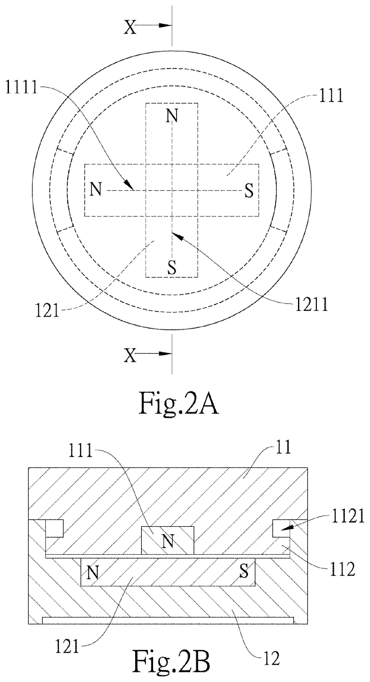
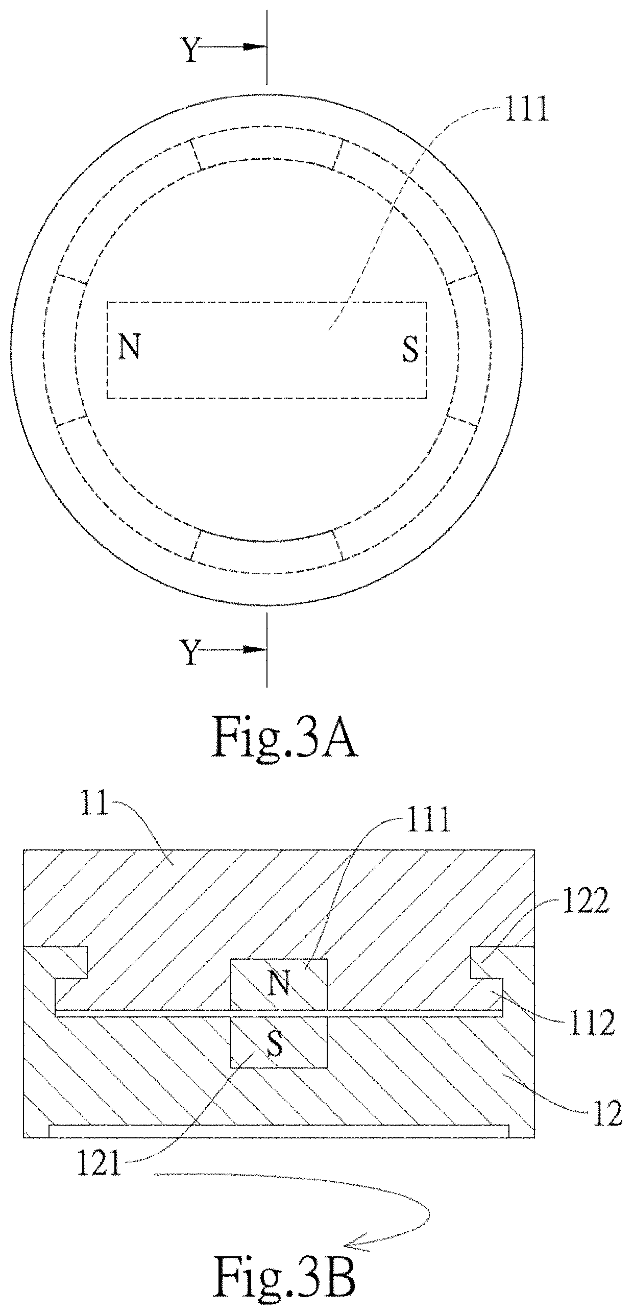
[0071]In the present disclosure, when the user start to make the first main body (11) and the second main body (12) mutually close, the second buckle structure (122) penetrates the notch (1122) and is disposed at the tail terminal of the groove (1121), and the first magnetic component (111) and the second magnetic component (121) are vertical to each other (as shown in FIG. 2A and FIG. 2B). Meanwhile, merely a little force is needed to slightly rotate the first main body (11) or the second main body (12), so as to make the first main body (11) or the second main body (12) be rotated slightly in respect to the rotation axis (A), and then, the N pole of the first main body (11) and the S pole of the second main body (12) generate the magnetic attraction effect, so as to make the first main body (11) or the second main body (12) be automatically rotated in respect to the rotation axis (A), for example, the second buckle structure (122) (i.e. or the protrusion block) is automatically mo...

second embodiment

[0077]Furthermore, referring to FIG. 6A, FIG. 6B, FIG. 7A and FIG. 7B simultaneously, which illustrate the magnetic assembly structure of the present disclosure, the first main body (11) comprises the two first magnetic components (111) and the two first buckle structures (112), wherein the two first magnetic components (111) are symmetrically disposed on the first main body (11), and the two first buckle structures (112) are symmetrically disposed on the first main body (11). The second main body (12) also comprises the two second magnetic components (121) and the two second buckle structures (122), the two second magnetic components (121) are symmetrically disposed on the second main body (12), and the two second buckle structures (122) are symmetrically disposed on the second main body (12). The two first magnetic components (111) are poles of same polarities, for example, both of them are the N poles or the S poles, and the two second magnetic components (121) are poles of same ...

fifth embodiment

[0085]Refer to FIG. 13A through FIG. 13D, which respectively are an explosive diagram of a magnetic assembly structure according to the present disclosure, a sectional view a first main body of a line 13B-13B, a sectional view a second main body of a line 13C-13C, a sectional diagram showing the first main body and second main body mutually close. In the embodiment, the first buckle structure (112) is a flange, a top part of the first buckle structure (112) is formed with a groove (1121), and the second buckle structure (122) is a bump. When the user uses his / her hand to place the second buckle structure (122) of the second main body (12) to the groove (1121), since the first main body (11) and the second main body (12) mutually generate a magnetic attraction or repulsion effect to automatically rotate the second main body (12) and first main body (11) in respect to each other, the bump is able to move in the groove (1121). Thus, the second buckle structure (122) automatically moves...


PUM


Abstract

The present disclosure relates to a magnetic assembly structure which utilizes a magnetic attraction or repulsion effect generated by two magnetic components to make two buckle structures automatically engaged to each other. The magnetic assembly structure of the present disclosure has a first main body and a second main body, and via the hardware design of disposing magnetic components and buckle structures respectively on the first main body and the second main body, the first and second main bodies rotate in respect to each other due to the magnetic attraction or repulsion effect, so as to efficiently engage the two buckle structures each other. Thus, it actually eases the installation and uninstallation of the appliance to which the magnetic assembly structure is applied, and the costs of installation and consuming time are reduced.

Description

CROSS REFERENCE[0001]The present invention is Continuation-in-part application of U.S. patent application Ser. No. 16 / 014,180 filed on 2018 Jun. 21, wherein all contents of the references which priorities are claimed by the present invention are included in the present invention, herein.BACKGROUND1. Technical Field[0002]The present disclosure relates to a magnetic assembly structure, in particular, to a magnetic assembly structure which utilizes a magnetic attraction or repulsion effect generated by two magnetic components to make two buckle structures automatically engaged to each other.2. Description of Related Art[0003]Generally, to assemble two main bodies to an object, a screwing way can be used by screws, or an engaging or snapping way can be used by buckle structures. For example, a thermos cup has a cup body and a cup cover, which respectively have a male screw and female screw, and thus a rotating way can be used to snap the male screw and the female screw. Usually, a left ...

Claims


Application Information

Patent Timeline
IPC IPC(8): F21V21/096F21V21/30
CPCF21V21/096F21V21/30F21V21/03H01R13/6205H01R11/30H01R4/54H01F7/0263
Inventor LEE, WEI-LONGLIAO, SHIH-MENG
Owner TAIWAN OASIS TECH CO LTD
Learn More