
Lidar system with solid state spectral scanning

a solid-state spectral scanning and detector technology, applied in the field of light detection and range (lidar), can solve the problems of reducing coupling efficiency and severely degrading target signals from distant objects

Active Publication Date: 2020-12-24
AEVA INC
View PDF0 Cites 31 Cited by
  • Summary
  • Abstract
  • Description
  • Claims
  • Application Information

AI Technical Summary

Benefits of technology

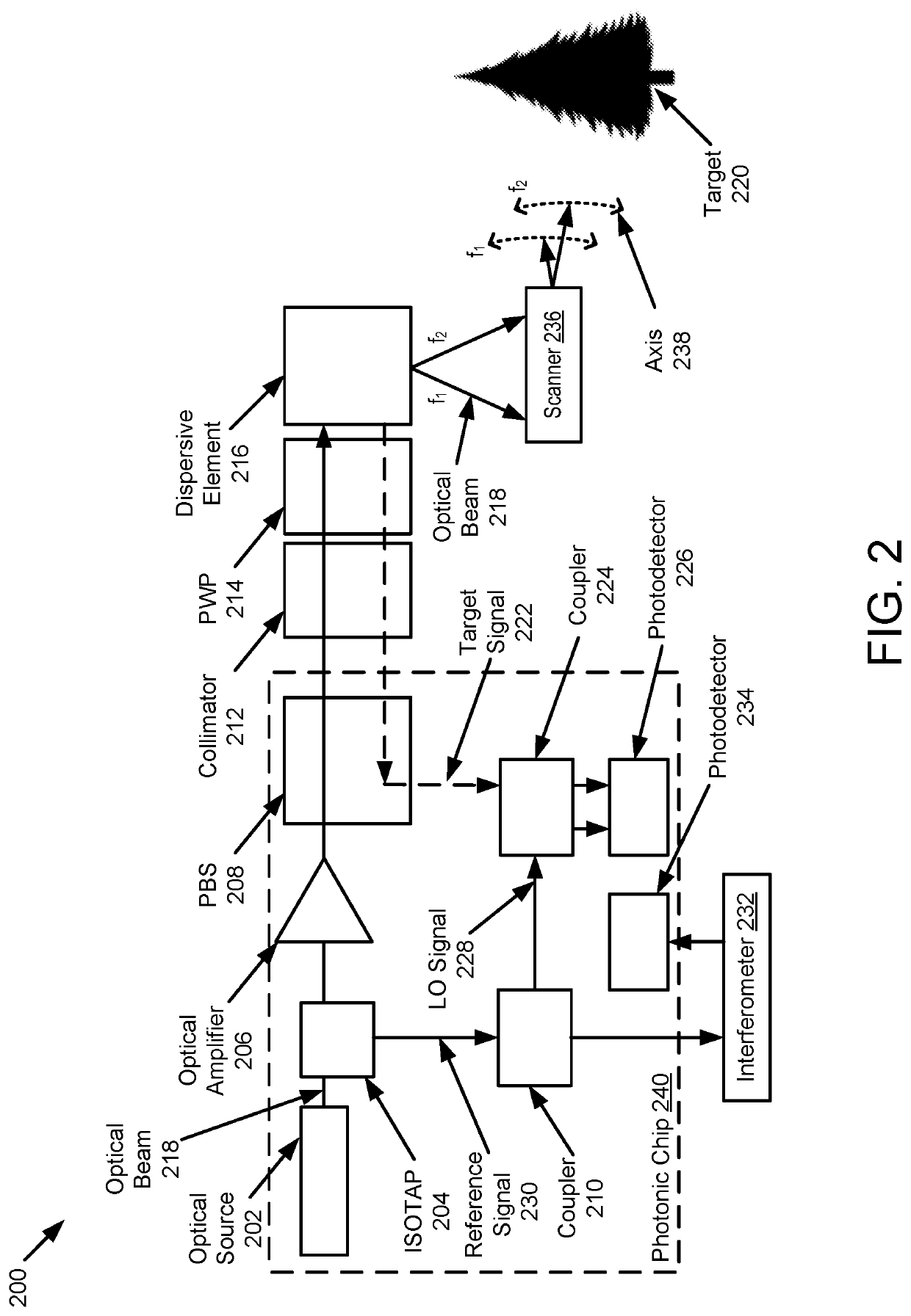
The patent is about a device called LIDAR that can detect and measure the distance of objects using light beams. The device includes an optical source that emits two beams of light with different frequencies. A dispersive element then deflects one of the beams at a different angle than the other. This results in the beams hitting different points on the object being measured. The device can then capture the light that is reflected or scattered from the object and analyze it to determine the distance of the object. The technical effect of this patent is to provide a more accurate and efficient way to measure distances of objects using LIDAR technology.

Problems solved by technology

When using the mirrors with a high angular velocity and single-mode fiber-based detection, the target signal from distant objects is severely degraded.
This slight angular change causes a walk-off of the target signal at the fiber tip decreasing the coupling efficiency, which manifests itself as a weaker signal detection.

Method used


Image

  • Lidar system with solid state spectral scanning
  • Lidar system with solid state spectral scanning
  • Lidar system with solid state spectral scanning

Examples


Embodiment Construction

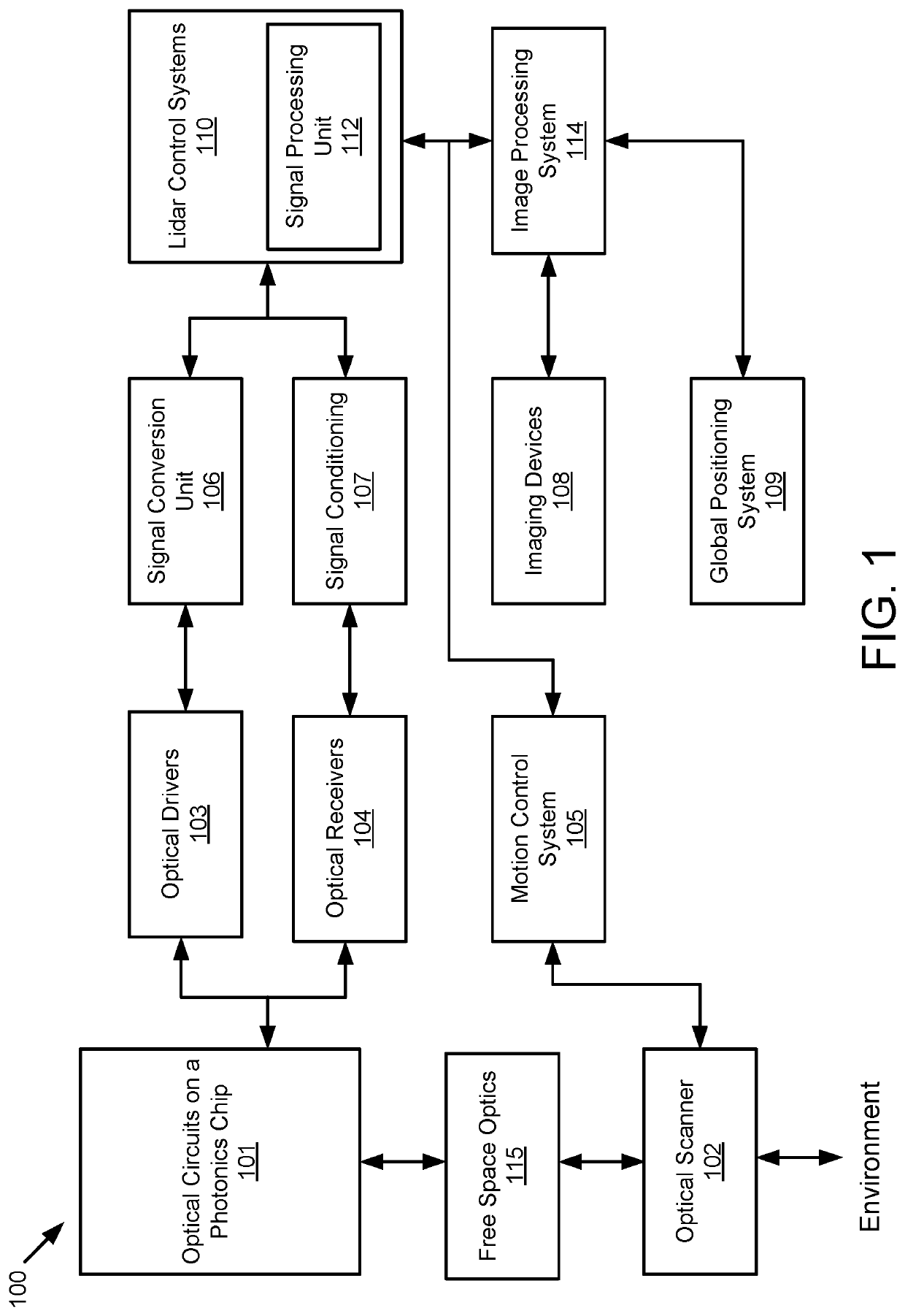
[0019]Example implementations of the present disclosure are directed to an improved scanning LIDAR system. Example implementations of the present disclosure are based on a type of LIDAR that uses frequency modulation (FM) and coherent detection to overcome the shortcomings of traditional LIDAR systems and the limitations of prior FM LIDAR systems. Historically, FM LIDAR systems suffer from significant losses in the beam's return path; thus, such systems, which are often quite bulky, require a higher average beam output power to measure distances comparable to time-of-flight (TOF) LIDAR systems. However, the range is limited by the operating distance for eye-safe output powers.

[0020]Example implementations of the present disclosure are configured to simultaneously measure the range and velocity, using coherent detection and having the added benefit of immunity to crosstalk from other LIDAR systems. Other implementations may be used with incoherent systems to improve, range, frame rat...


PUM


Abstract

A light detection and ranging (LIDAR) apparatus is provided that includes an optical source to emit a first optical beam having a first frequency and a second optical beam having a second frequency and a dispersive element to deflect the first optical beam having the first frequency at a first angle and the second optical beam having the second frequency at a second angle.

Description

TECHNICAL FIELD[0001]The present disclosure relates generally to light detection and ranging (LIDAR) that provides simultaneous measurement of range and velocity across two dimensions.BACKGROUND[0002]Fast-scanning mirrors are the primary components used to illuminate a scene in most conventional LIDAR systems. One mirror typically scans quickly along the X direction (azimuth), while another mirror scans slowly along the Y direction (elevation). Light emission and detection from target reflections are done coaxially, typically via a single-mode fiber. The collected light has a measured delay or an altered frequency signature that is used to extract range, and potentially velocity, information. A 3D point cloud can be established when the point-wise detected range information is combined with angular position feedback from the scanning mirrors.[0003]To achieve higher frame rates, the mirror's angular velocity is increased, especially that of the scanner in faster scan direction (X sca...

Claims


Application Information

Patent Timeline
IPC IPC(8): G01S7/491G01S7/481G01S17/08
CPCG01S7/4911G01S17/08G01S7/4814G01S7/4817G01S17/89G01S17/42G01S7/4816
Inventor REZK, MINAKOCAOGLU, OMER P.AVCI, OGUZHANOZA, NEAL N.GAGNE, KEITHBEHZADI, BEHSAN
Owner AEVA INC
Learn More