
System and Method for Collection and distribution of Space Based Solar Power

a space-based solar power and solar energy technology, applied in the field of ground, atmospheric and space-based solar powered electrical energy generation and transmission of beamed microwave power, can solve the problem that the risk of a single failure of a single transmitter is too great, and the reliance on a single transmitter to synchronize all local oscillators is too grea

Active Publication Date: 2020-12-17
HYLAND DAVID C +1
View PDF0 Cites 1 Cited by
  • Summary
  • Abstract
  • Description
  • Claims
  • Application Information

AI Technical Summary

Benefits of technology

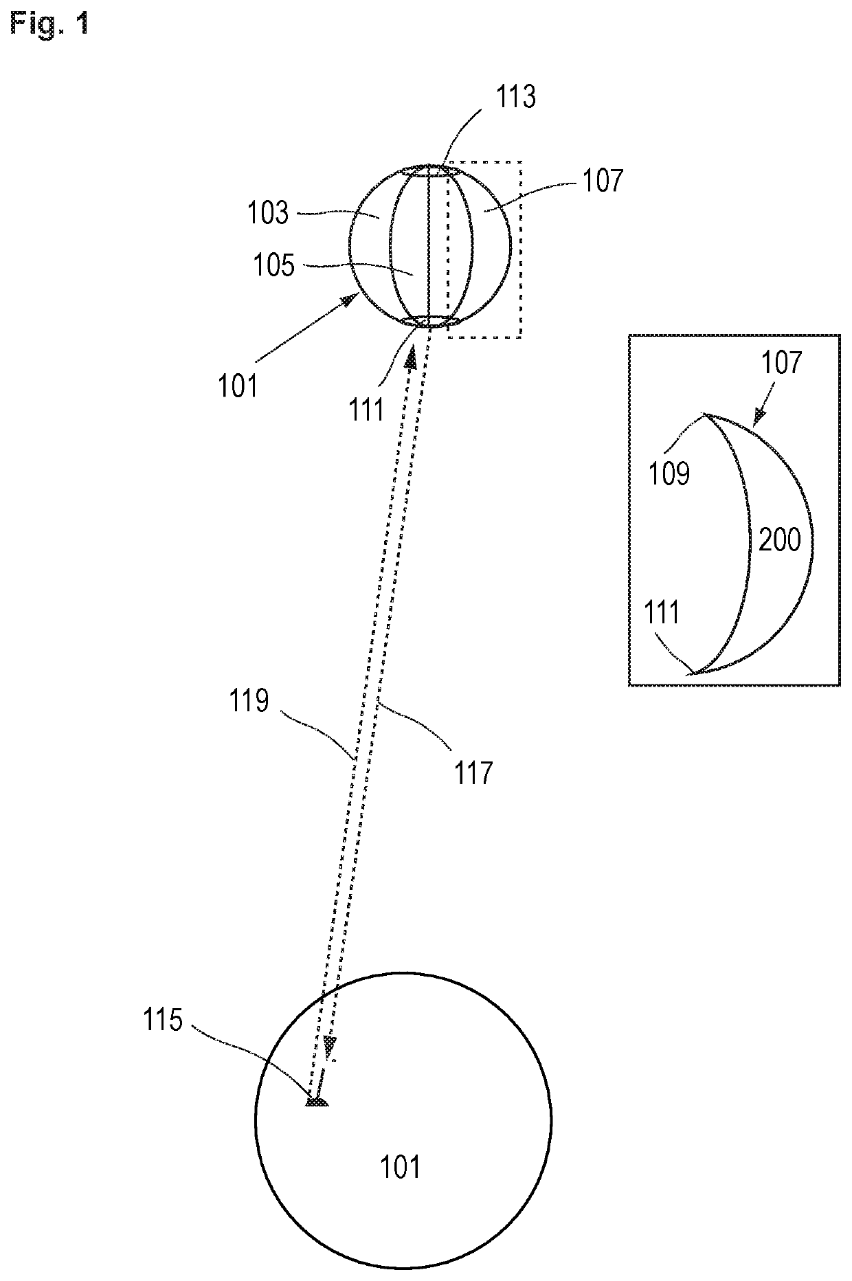
The patent text describes a microwave energy transmission system that can be used to disable aircraft or rockets at a distance of tens of kilometers. It is also useful to protect against incoming artillery and mortar shells by thermally detonating their explosive payloads or destroying their fuse electronics by the EMF effects of the high energy microwaves. The system uses a solar power collection balloon that can manipulate its own orbit while providing a service to a target. The balloon can conduct a combination of orbital boosts and decays upon various targets to perform maintenance on its own orbit. Overall, the technical effects of this invention include a powerful microwave energy transmission system and a novel method to maintain the solar power collection balloon's orbit.

Problems solved by technology

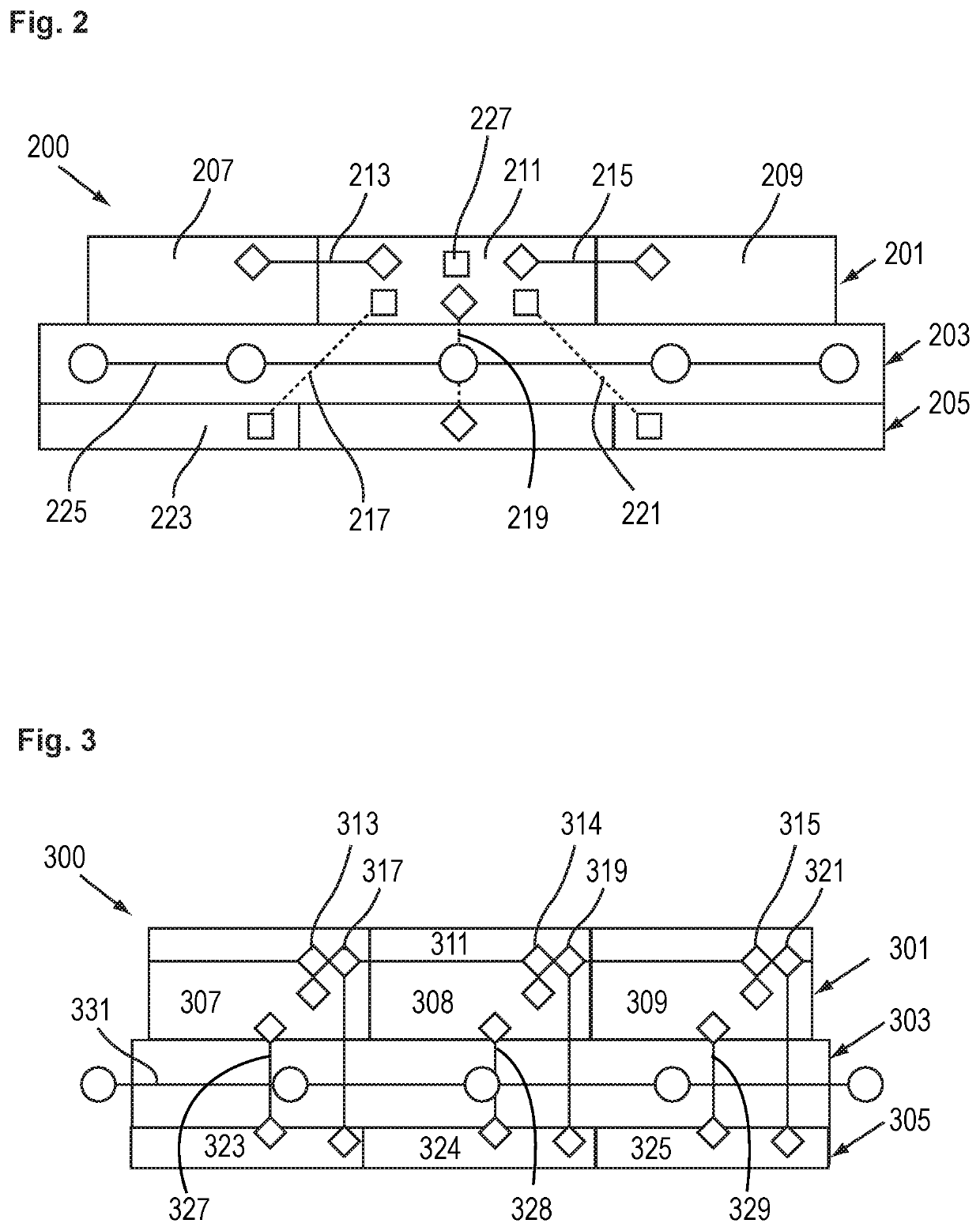
This is not an ideal arrangement because the grating lobes have a negative effect on the accuracy with which a desired power distribution may be approximated as the actual produced distribution is the convolution of the desired distribution and the point spread function.
Reliance on a single transmitter to synchronize all of the local oscillators might bear the risk of a single point of failure.

Method used


Image

  • System and Method for Collection and distribution of Space Based Solar Power
  • System and Method for Collection and distribution of Space Based Solar Power
  • System and Method for Collection and distribution of Space Based Solar Power

Examples


Embodiment Construction

[0036]This embodiment the invention is built and operated with the internal transceivers omitted and with the addition of an “active” mode of power transmission whereby radiation is broadcast to a non-cooperative target and the return from the target is used as the beacon for direction of a high power density beam.

[0037]In the power gathering mode, the Power / Com / Defense embodiment simply uses the printed solar array elements. As pictured in FIG. 9, a compactly folded rug of fabric is brought to a forward military base, a developing world location or similarly difficult to access location and is then unfolded. and spread over the ground. Once deployed, it provides solar power using the printed solar cells and a conventional power management and distribution system. FIG. 9 shows ground based power system 900 including power fabric rug 901 functionally connected to a power distribution center 903 by power cable 902.

[0038]Besides providing power, this embodiment can be run in “active” r...


PUM


Abstract

The present invention generally is a system and method for ground, atmospheric and space based solar powered electrical energy generation and transmission of beamed microwave power. Specifically it is a system and method for generating electrical energy from a plurality of photovoltaic cells dispersed on a flexible surface each in close proximity to and functionally connected to microwave generating and transmitting means for controllably forming one or more stronger microwave beams by combining a plurality of much weaker individual microwave beams. The invention can be a microwave beam weapon for detecting and transferring microwave energy to non-cooperative targets or it clear orbital debris by momentum transfer to space object through microwave radiation pressure. Most practically it can provide electric power and microwave beam weapon defense to remote military and civilian facilities, including forward operating bases.

Description

CROSS-REFERENCE TO RELATED APPLICATIONS[0001]The present application is a continuation in part of Ser. No. 15 / 328,367 filed Jan. 23, 2017 and claims the benefit of PCT Application no. 2015041854 filed Jul. 23, 2015, provisional application No. 62 / 028,000 filed Jul. 23, 2014 and 62 / 148,570 filed Apr. 16, 2015, all of which are incorporated herein by reference.FIELD OF THE INVENTION[0002]The present invention generally relates to ground, atmospheric and space based solar powered electrical energy generation and transmission of beamed microwave power and in particular, a system and method for generating electrical energy from a plurality of photovoltaic cells dispersed on a flexible surface that are each in close proximity to and functionally connected to microwave generating and transmitting means for controllably forming one or more stronger microwave beams by combining a larger plurality of weaker individual microwave beams. The field of this invention includes microwave beam weapon...

Claims


Application Information

Patent Timeline
IPC IPC(8): H02J50/23H02S10/00H02J50/40H02J50/27B64G1/44B64G1/22B64G1/10B64G1/66
CPCB64G1/10H02S10/00H02J50/27H02J50/23B64G1/222B64G1/66B64G1/443H02J50/40B64G1/44B64G1/407B64G1/62H02S10/40H02S20/30Y02E10/50B64G1/2227B64G1/2222B64G1/4282
Inventor HYLAND, DAVID C.ALTWAIJRY, HAITHEM A.
Owner HYLAND DAVID C
Learn More