
Nozzle hanger

a technology of nozzles and hangers, which is applied in the direction of container filling under pressure, liquid transfer devices, transportation and packaging, etc. it can solve the problems of heavy load on the filler, the filling nozzle cannot be removed from the nozzle hanger, and the filling nozzle cannot be connected to the filling port of the vehicle, so as to achieve convenient, fast and reliable hung and removal

Pending Publication Date: 2020-12-10
TOKYO TATSUNO CO LTD
View PDF0 Cites 0 Cited by
  • Summary
  • Abstract
  • Description
  • Claims
  • Application Information

AI Technical Summary

Benefits of technology

The present invention provides a nozzle hanger that can easily, quickly, and reliably hang and remove a filling nozzle, and can also handle pre-cool filling. The nozzle hanger is made of a single integrated member, which reduces manufacturing and mounting errors, and prevents dimensional errors between the filling nozzle and the nozzle hanger. The movable lock section includes biasing means to prevent the filling nozzle from dropping out of the nozzle hanger. The fixed lock section has a recessed section and a stepped section to securely hold the filling nozzle. Overall, the nozzle hanger of the present invention ensures the stability and reliability of the filling process.

Problems solved by technology

The above-mentioned conventional nozzle hanger is separately provided with a hook and a lid part, so that manufacturing errors and mounting errors of these members cause a hanging condition of the filling nozzle on the nozzle hanger to change, which may cause dropout of the filling nozzle from the nozzle hanger.
Furthermore, in the conventional nozzle hanger, only a gap of one hand is left between the upper and lower members for holding the filling nozzle excluding the filling nozzle, so that a filler has to hang and remove the filling nozzle with one hand, which is a heavy burden for the filler.
Further, due to the above pre-cool filling, the filling nozzle connected to a filling port of a vehicle is cooled, and a movable part such as a lever or a fixed part such as a discharge pipe may freeze, which may make it impossible to remove the filling nozzle from the filling port of the vehicle, or to connect the filling nozzle to the filling port of the vehicle at the next filling.

Method used


Image

  • Nozzle hanger
  • Nozzle hanger
  • Nozzle hanger

Examples


Embodiment Construction

[0024]Hereinafter, embodiments of the present invention will be explained with reference to the attached drawings.

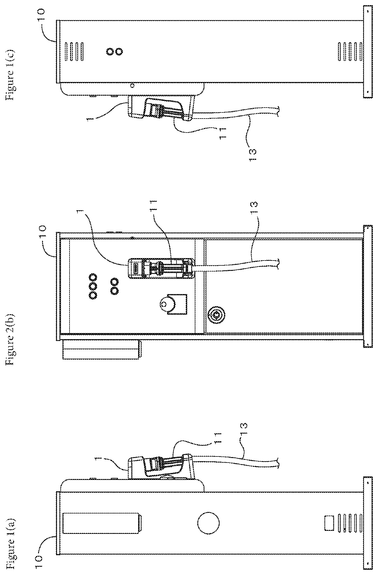
[0025]FIGS. 1(a), 1(b) and 1(c) show an example of a gas filling apparatus with a nozzle hanger according to the present invention, the nozzle hanger 1 of the present invention is mounted at a central portion on the front of the gas filling apparatus 10. The figure shows a condition that a filling nozzle 11 attached to an end portion of a filling hose 13 is hung on the nozzle hanger 1.

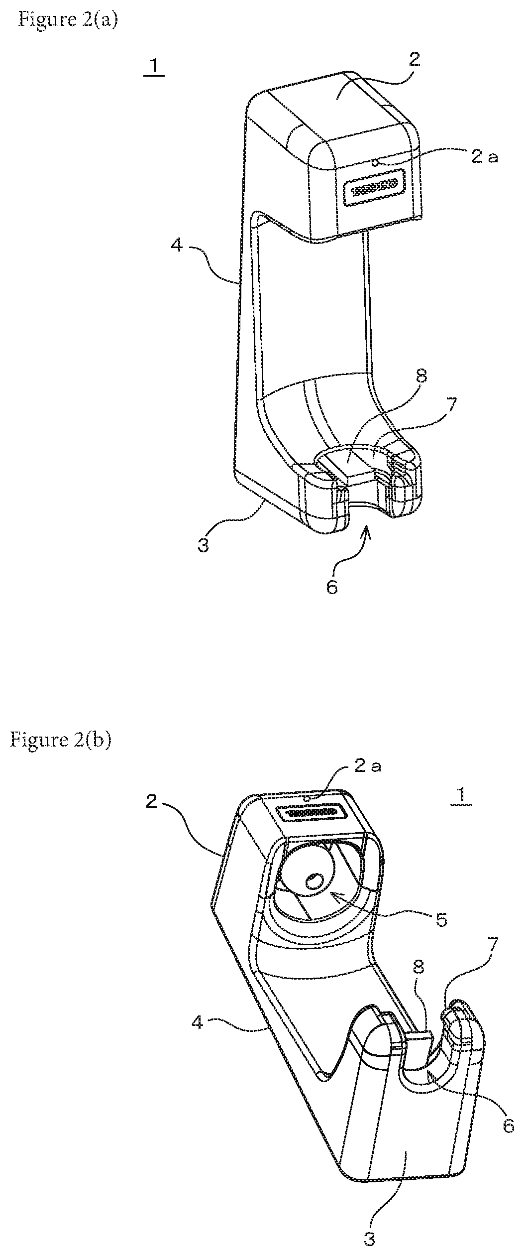
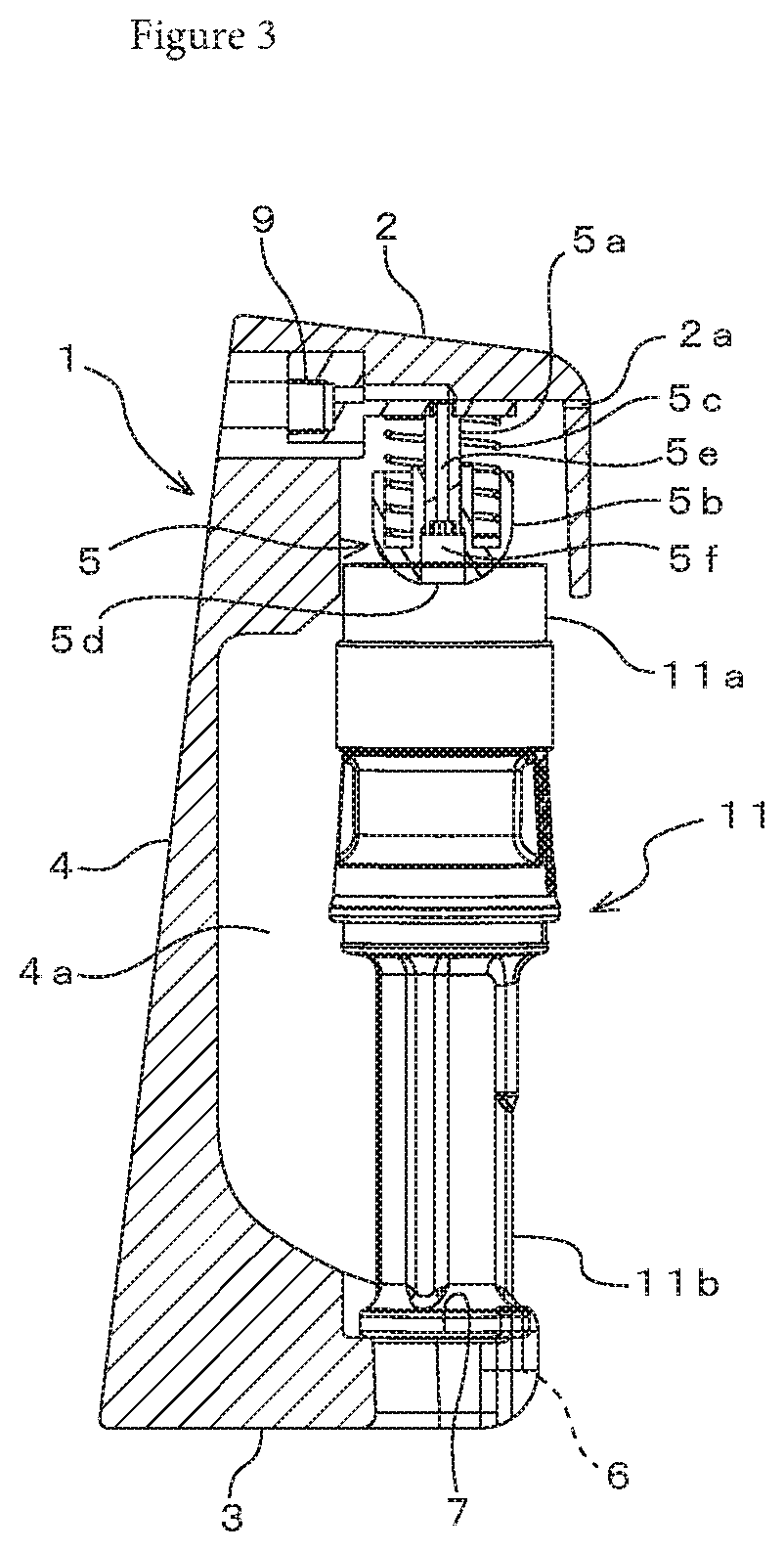
[0026]The nozzle hanger 1 roughly includes, as shown in FIGS. 2(a), 2(b) and 3, an upper part 2 for holding a filling pipe 11a of the filling nozzle 11, and a lower part 3 for holding a grip section 11b of the filling nozzle 11, and an intermediate part 4 for connecting the upper part 2 and the lower part 3.

[0027]The upper part 2 is provided with a movable lock section 5 for locking the filling pipe 11a of the filling nozzle 11. The movable lock section 5 is composed of a shaft member 5a ve...


PUM


Abstract

To provide a nozzle hanger on which a filling nozzle can be easily, quickly, and reliably hung and removed, and which can also handle pre-cool filling. A nozzle hanger 1 for hanging a filling nozzle 11, of which one end has a filling pipe 11a for filling a hydrogen gas and the other end has a grip section 11b, is provided with: an upper part 2 that holds the filling pipe of the filling nozzle; a lower part 3 that faces the upper part and holds the grip section of the filling nozzle; and an intermediate part 4 that connects the upper part and the lower part, wherein the lower part is provided with a fixed lock section (a recessed section 6, a stepped section 7) that locks the grip section of the filling nozzle in a fixed state, and the upper part is provided with a movable lock section 5 that contacts the filling pipe of the filling nozzle and locks the filling pipe in a movable state. The movable lock section can be provided with biasing means (a spring 5c) that biases the filling pipe downward when the filling nozzle is hung on the nozzle hanger. The movable lock section is formed in a spherical shape that protrudes downward, and a gas outlet 5d can be provided in a central region thereof.

Description

CROSS-REFERENCE TO RELATED APPLICATIONS[0001]The present application claims priority to International Application No. PCT / JP2018 / 041987 filed on Nov. 13, 2018, which claims priority to Japanese Patent Application No. 2018-018030 filed on Feb. 5, 2018, the disclosures of which are incorporated herein by reference.STATEMENT RE: FEDERALLY SPONSORED RESEARCH / DEVELOPMENT[0002]Not ApplicableBACKGROUND1. Technical Field of the Invention[0003]The present invention relates to a nozzle hanger on which a hydrogen filling nozzle is hung in a hydrogen filling apparatus.2. Description of the Related Art[0004]In a hydrogen filling apparatus installed at a hydrogen station, a filling nozzle attached to an end of a filling hose is removed from a nozzle hanger of the hydrogen filling apparatus, and is connected to a filling port of a vehicle to fill a hydrogen gas in a hydrogen tank of the vehicle. In order to hang the filling nozzle on the nozzle hanger, for example, after inserting a lower end of t...

Claims


Application Information

Patent Timeline
Patent Type & Authority Applications(United States)
IPC IPC(8): B05B15/60F17C5/06
CPCB05B15/60F17C5/06F17C2221/012F17C2205/0376F17C2205/0352Y02E60/32F17C2223/0123F17C2223/036F17C2270/0139B05B15/555B67D7/06Y02P90/45
Inventor TAKEZAWA, MASAHIROARAI, MAKOTO
Owner TOKYO TATSUNO CO LTD
Learn More