
Apparatus for measuring position and shape of pattern formed on sheet

Inactive Publication Date: 2012-04-05
YOKOGAWA ELECTRIC CORP
View PDF16 Cites 5 Cited by
  • Summary
  • Abstract
  • Description
  • Claims
  • Application Information

AI Technical Summary

Benefits of technology

[0022]Even when a lens such as an above-described lens 30 is used, by reducing the angle of field of the lens 30, effects caused by the variation in the optical axis direction can be reduced.
[0024]In FIGS. 7A and 7B, B and B′ are illustrated at horizontally shifted positions for explanatory purposes. Actually, both of B and B′ are located on the image pickup elements at the same position. As can be seen from FIG. 7B, B′ is a larger image than B. However, compared to the case illustrated in FIG. 7A, the ratio of the change is decreased in FIG. 7B. Although movement of the sheet 1 to be measured from A to A′ slightly changes the size of the image, effects produced by this change are smaller than those in the case where the field of angle is larger. Thus, errors in dimensions can be reduced.
[0028]Accordingly, an object of the present application is to provide an apparatus for measuring the position and shape of a pattern formed on a sheet as follows. That is, with this measuring apparatus, in inspecting a width and a length of a coating pattern with cameras, a need for replacement or modification of the measuring apparatus is substantially eliminated even when there is a change in the number and positions of images to be picked up caused by a change in the width of the sheet or the number of rows of a coating material applied on the sheet in the width direction. In this case, high flexibility of the measuring apparatus is achieved at a low cost, and calibration performed in measuring a position and shape is simplified.
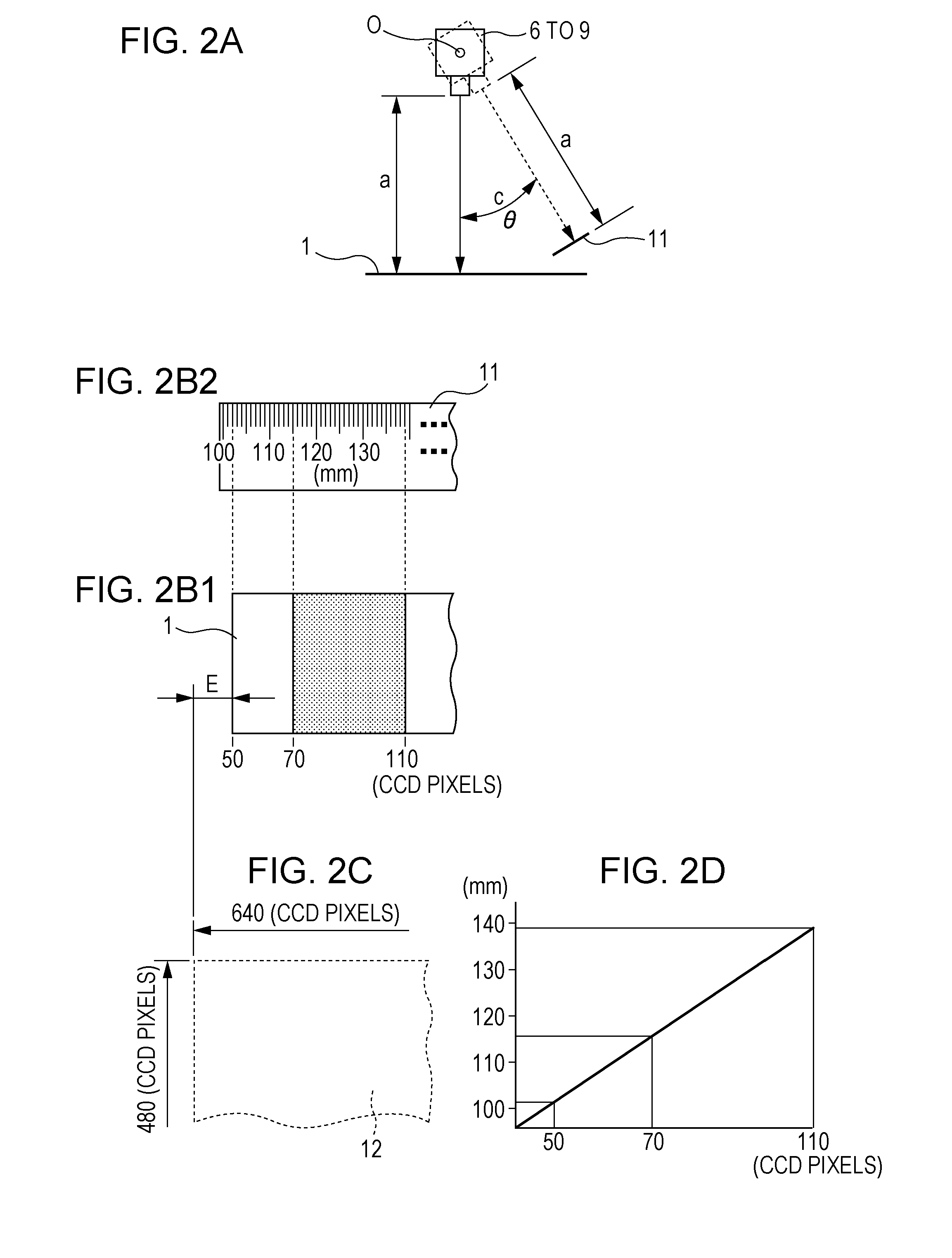
[0031]In this case, the image of the position and the shape of a coating portion and the image of the reference body for calibration can be suitably compared, and accordingly, errors in measurement due to deviations in mechanical dimensions of a camera system can be minimized.
[0034]In this case, mirror is provided in the field of view of the camera, thereby including the reference body for calibration in the field of view together with the coating portion, and light such as laser light is emitted so as to project a dimensional reference position on the sheet to be measured, thereby comparing the projected reference position with the coating portion. This eliminates a need for a moving mechanism for the camera system, and accordingly, prevents generation of dust, occurrence of problems related to the life, and other problems occurring due to the moving mechanism.
[0036]In this case, the cameras can be arbitrarily moved to positions corresponding to measurement targets in accordance with the number of rows of coating. Thus, there is no need for arranging the number of cameras sufficient to cover the entire width of coating, and accordingly, the numbers of cameras, the size of the image input board, and the like can be minimized, thereby realizing manufacture of the apparatus at a low cost.

Problems solved by technology

This prevents correct measurement of the dimensions.

Method used


Image

  • Apparatus for measuring position and shape of pattern formed on sheet
  • Apparatus for measuring position and shape of pattern formed on sheet
  • Apparatus for measuring position and shape of pattern formed on sheet

Examples


Embodiment Construction

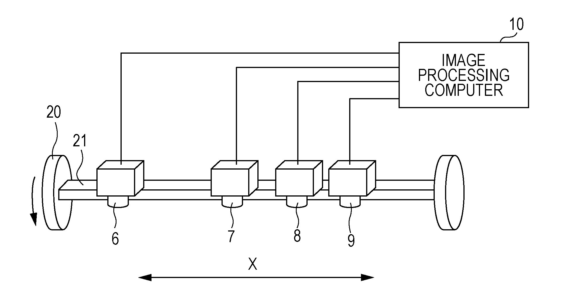
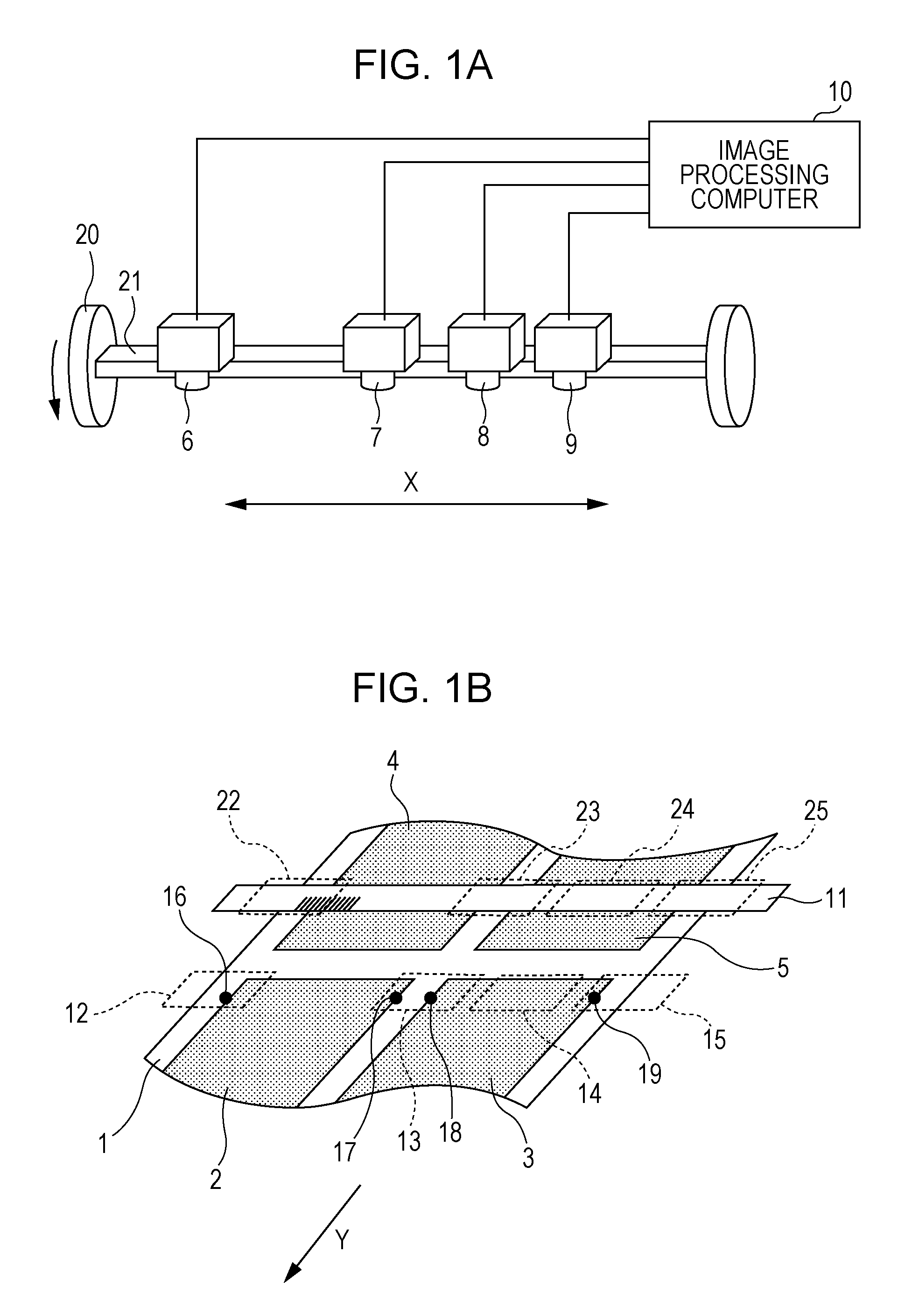
[0045]The present disclosure will be described below in detail with reference to the drawings. FIGS. 1A and 1B are schematic diagrams illustrating an apparatus for measuring the position and shape of a coating pattern as an example of an embodiment according to the present invention.

[0046]Referring to FIG. 1B, coating patterns 2 to 5 are coated on a sheet 1. The sheet 1 is transported on a conveyor (not shown) from the rear side to the front side of the drawing sheet at a constant speed.

[0047]FIGS. 2A to 2D are diagrams for explaining a state of an image pickup screen when a camera holding mechanism 21 illustrated in FIG. 1A is rotated through 8 degrees toward the upstream of a flow of the sheet 1.

[0048]In these drawings, the camera holding mechanism 21 is disposed in a direction perpendicular to (an arrow X direction) a direction of the flow of the sheet 1 (an arrow Y direction). In the camera holding mechanism 21, four cameras 6 to 9 are linearly spaced apart in a longitudinal dir...


PUM


Abstract

An apparatus for measuring the position and shape of a pattern formed on a sheet includes a sheet on which a pattern is formed, a camera holding mechanism that is disposed perpendicular to a transportation direction of the sheet, at least one camera that is disposed such that the camera is movable in a longitudinal direction of the camera holding mechanism, and an image processing computer that processes an image picked up by the at least one camera. In the measuring apparatus, when calibration is performed, calibration is performed with reference to a picked up image of the coating pattern and a picked up image of a reference body for calibration.

Description

[0001]The present application is based upon and claims the benefit of priority from the prior Japanese Patent Application No. 2010-220307, filed on Sep. 30, 2010, the entire contents of which are incorporated herein by reference.BACKGROUND OF THE INVENTION[0002]1. Field of the Invention[0003]The present disclosure relates to an apparatus for measuring the position and shape of a pattern that is formed on, for example, a sheet-shaped base material by coating or printing.[0004]2. Description of the Related Art[0005]In processes of manufacturing, for example, electrodes for capacitors or batteries, materials (coating substances) that realize specific electrical properties are applied to sheet base materials (simply referred to as sheets hereinafter). In this case, the coating substance is sometimes applied over the entire surface of a sheet. However, when the coating substance is expensive or the edge surfaces of the sheet need be free of the coating substance, only specified portions ...

Claims


Application Information

Patent Timeline
IPC IPC(8): H04N7/18
CPCG01N21/8903H04N7/18H04N5/225H04N23/00
Inventor ICHIZAWA, YASUSHICHIDA, NAOMICHIAKUTSU, MINORU
Owner YOKOGAWA ELECTRIC CORP
Learn More