
Ink-jet head, filter assembly used for manufacturing the ink-jet head, and method for manufacturing the ink-jet head using the filter assembly

a filter assembly and inkjet head technology, applied in printing and other directions, can solve the problems of affecting the quality of printing, so as to reduce the variation of passage resistance, improve printing quality, and facilitate the effect of printing

Inactive Publication Date: 2006-05-04
BROTHER KOGYO KK
View PDF16 Cites 2 Cited by
  • Summary
  • Abstract
  • Description
  • Claims
  • Application Information

AI Technical Summary

Benefits of technology

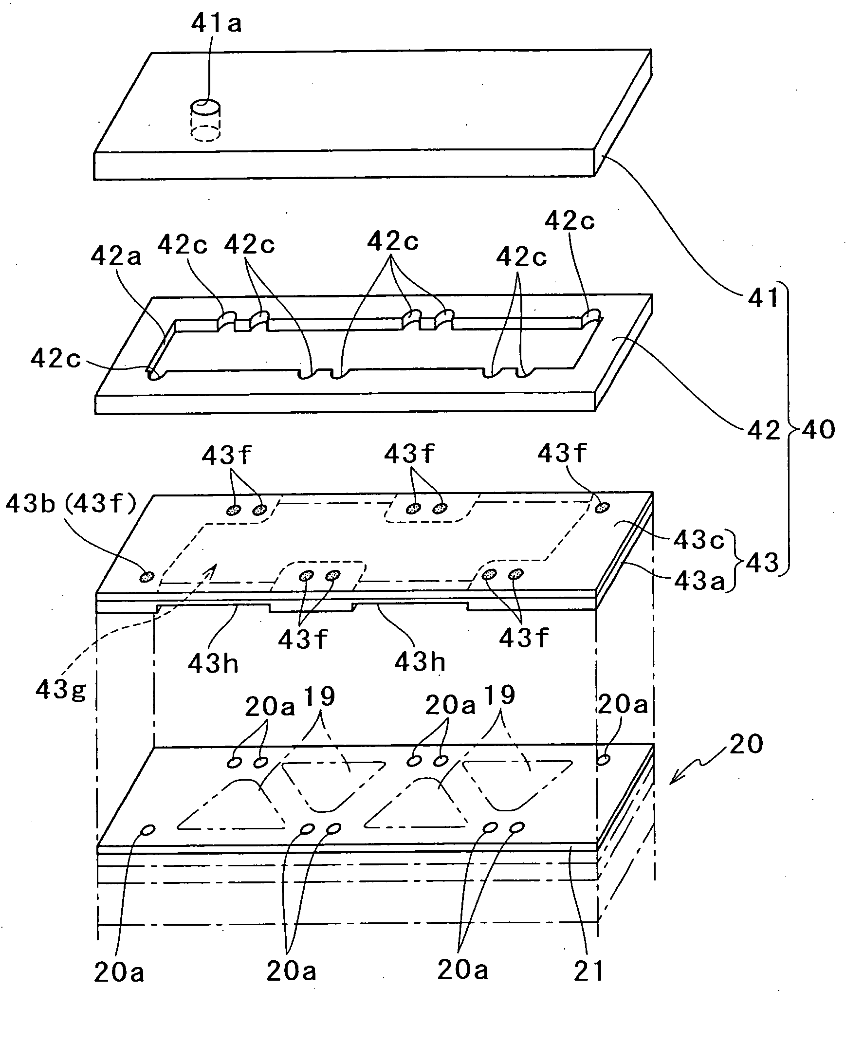
The present invention provides an ink-jet head with improved printing quality by reducing variations in ink passage resistance. This is achieved by using a filter assembly with a plurality of filter supporting members that are arranged on the surface of the ink passage unit. The filter supporting members are interconnected at bending points, and a filter is formed in each of the filter supporting members. The filter assembly is separated from the ink passage unit by bending the interconnecting points, and the filter supporting members are arranged on the surface of the passage unit so that the filter may face each ink inlet port. This allows for easier manufacturing and reduces dimensional errors of the filters.

Problems solved by technology

As a result, each filter becomes relatively small in size and relatively large in number.
In these cases, a dimensional error of the filter is often caused.
This dimensional error causes a variation of passage resistance in the individual ink passage each corresponding to an individual nozzle, thereby leading to deterioration of printing quality.

Method used


Image

  • Ink-jet head, filter assembly used for manufacturing the ink-jet head, and method for manufacturing the ink-jet head using the filter assembly
  • Ink-jet head, filter assembly used for manufacturing the ink-jet head, and method for manufacturing the ink-jet head using the filter assembly
  • Ink-jet head, filter assembly used for manufacturing the ink-jet head, and method for manufacturing the ink-jet head using the filter assembly

Examples


first embodiment

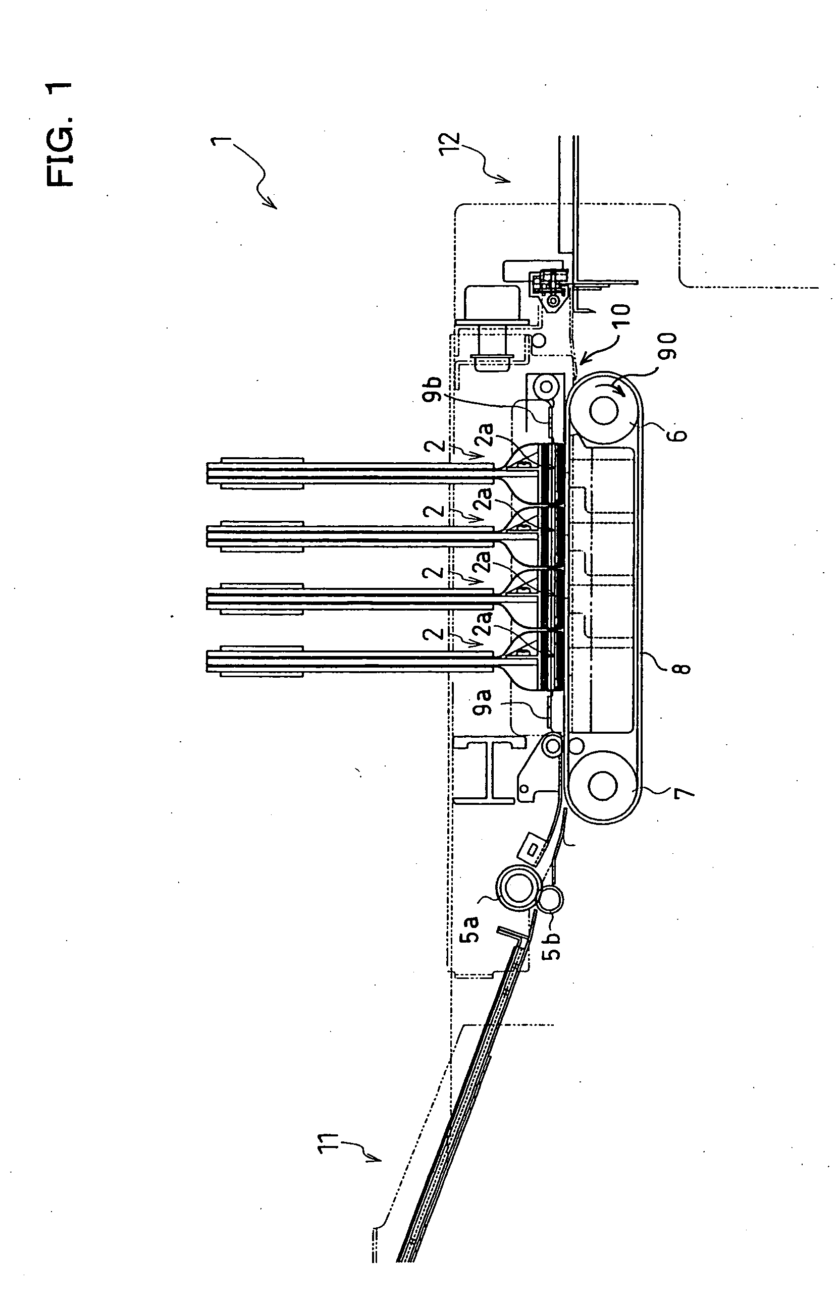
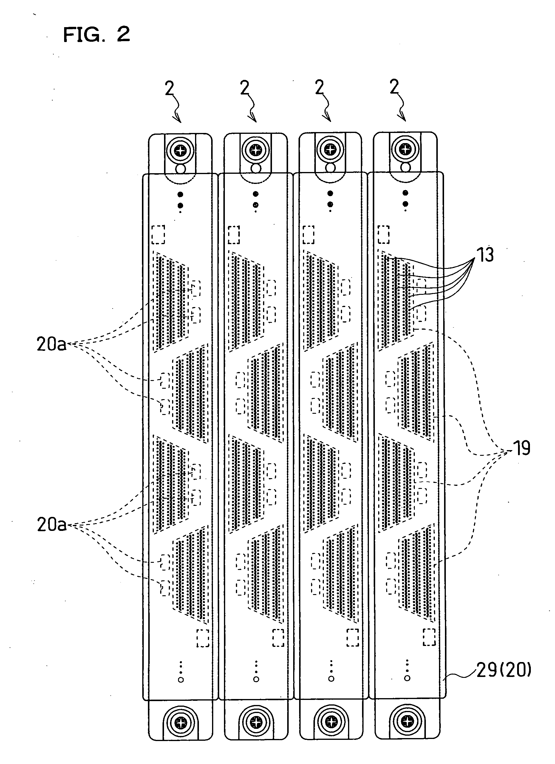
[0028]FIG. 1 illustrates a general construction of an example of a printer including ink-jet heads according to the present invention. The ink-jet printer 1 according to the present embodiment is a color ink-jet printer having four ink-jet heads 2. Within the ink-jet printer 1, a paper feed unit 11 and a paper discharge unit 12 are provided in left and right portions of FIG. 1, respectively. A paper conveyance path is formed extending from the paper feed unit 11 to the paper discharge unit 12 within the ink-jet printer 1.

[0029] A pair of paper feed rollers 5a and 5b are disposed immediately downstream of the paper feed unit 11 for putting forward paper as a medium from left to right in FIG. 1. In a middle of the paper conveyance path, two belt rollers 6 and 7 and a looped conveyor belt 8 are provided. The conveyor belt 8 is wrapped around each of the belt rollers 6 and 7 as to be stretched between them.

[0030] The conveyor belt 8 has a two-layered structure made up of a polyester ba...

second embodiment

[0078] Moreover, the construction in which the filter is disposed between the ink introduction port 51a and the ink reservoir 52a can provide wide variance in position, number, and shape, etc., of the filter. Accordingly, the filter can be formed at a position different from the position of the filter 53f in the second embodiment, and the number, size, and shape, etc., of the filter may properly be changed. When the filter is made smaller in number and larger in size, for example, a reduction of passage resistance in ink passages can further be restrained, and additionally, ink is prevented from inconveniently clogging at pores constituting the filter. Moreover, deficiencies in pores may frequently be caused in case of making a large number of small-diameter pores by etching, etc. In the present embodiment, however, this problem of deficiencies in pores can be decreased by enlarging the size of the filter. Further, it is also possible to give the filter a size and shape advantageous...

third embodiment

[0118] In the third embodiment, the filter supporting member 63 may be designed so as to cover any optional inlet port 20a.

[0119] In the third embodiment, moreover, a press working may be performed for manufacturing the filter assembly 73 so as to leave the filter supporting members 63, the interconnecting portions 73d, the peripheral connecting portions 73e, and the frame portion 73g, all of which are components.

[0120] In the third embodiment, moreover, it is satisfactory to form the interconnecting portions 73d and the peripheral connecting portions 73e to have such a strength as to avoid damaging during transportation of the filter assembly 73. Accordingly, both of the interconnecting portions 73d and the peripheral connecting portions 73e may be formed in either of the resin plate 73c and the metal plate 73a, and their number and position, etc., are not particularly limited.

[0121] In the third embodiment, moreover, the filter supporting members 63, the interconnecting portion...


PUM


Abstract

An ink-jet head comprises a passage unit with an ink passage formed therein and a branching passage unit, and is constructed by laminating the passage unit and the branching passage unit with each other. The ink passage extends from a common ink chamber for supplying ink to a pressure chamber toward a nozzle. The branching passage unit includes an ink branching passage for branching ink from an ink introduction port to ink outlet ports. The outlet ports leads out ink into the passage unit. Inlet ports for introducing ink into the common ink chamber are formed on a surface of the passage unit. Ink outlet ports in the branching passage unit are disposed so as to face the inlet ports. Filters for removing foreign matters mixed in ink are formed in the ink branching passage within the branching passage unit.

Description

[0001] This is a Divisional of application Ser. No. 10 / 667,495 filed Sep. 23, 2003. The entire disclosure of the prior application is hereby incorporated by reference herein in its entirety.BACKGROUND OF THE INVENTION [0002] 1. Field of the Invention [0003] The present invention relates to an ink-jet head for ejecting ink onto a record medium to print, a filter assembly used for the ink-jet head, and a method for manufacturing the ink-jet head using the filter assembly. [0004] 2. Description of Related Art [0005] In an ink-jet head, ink in an ink tank is lead to a supply passage, a common ink chamber, a pressure chamber, and then to a nozzle for ejecting the ink. Such a ink passage is formed by laminating a plurality of plates each formed with grooves or holes. [0006] An ink-jet head, in terms of printing quality, needs to include a filter for removing foreign matters mixed in ink. Thus, there are known such techniques that a filter is formed in a plate serving as a boundary between...

Claims


Application Information

Patent Timeline
Patent Type & Authority Applications(United States)
IPC IPC(8): B41J2/175B41J2/14
CPCB41J2/14209B41J2/17563B41J2002/14225B41J2002/14306B41J2002/14491
Inventor TAIRA, HIROSHI
Owner BROTHER KOGYO KK
Learn More