
Method and Apparatus for Real-Time Direct Membrane Monitoring

Active Publication Date: 2020-11-12
NORIA WATER TECH INC
View PDF0 Cites 3 Cited by
  • Summary
  • Abstract
  • Description
  • Claims
  • Application Information

AI Technical Summary

Benefits of technology

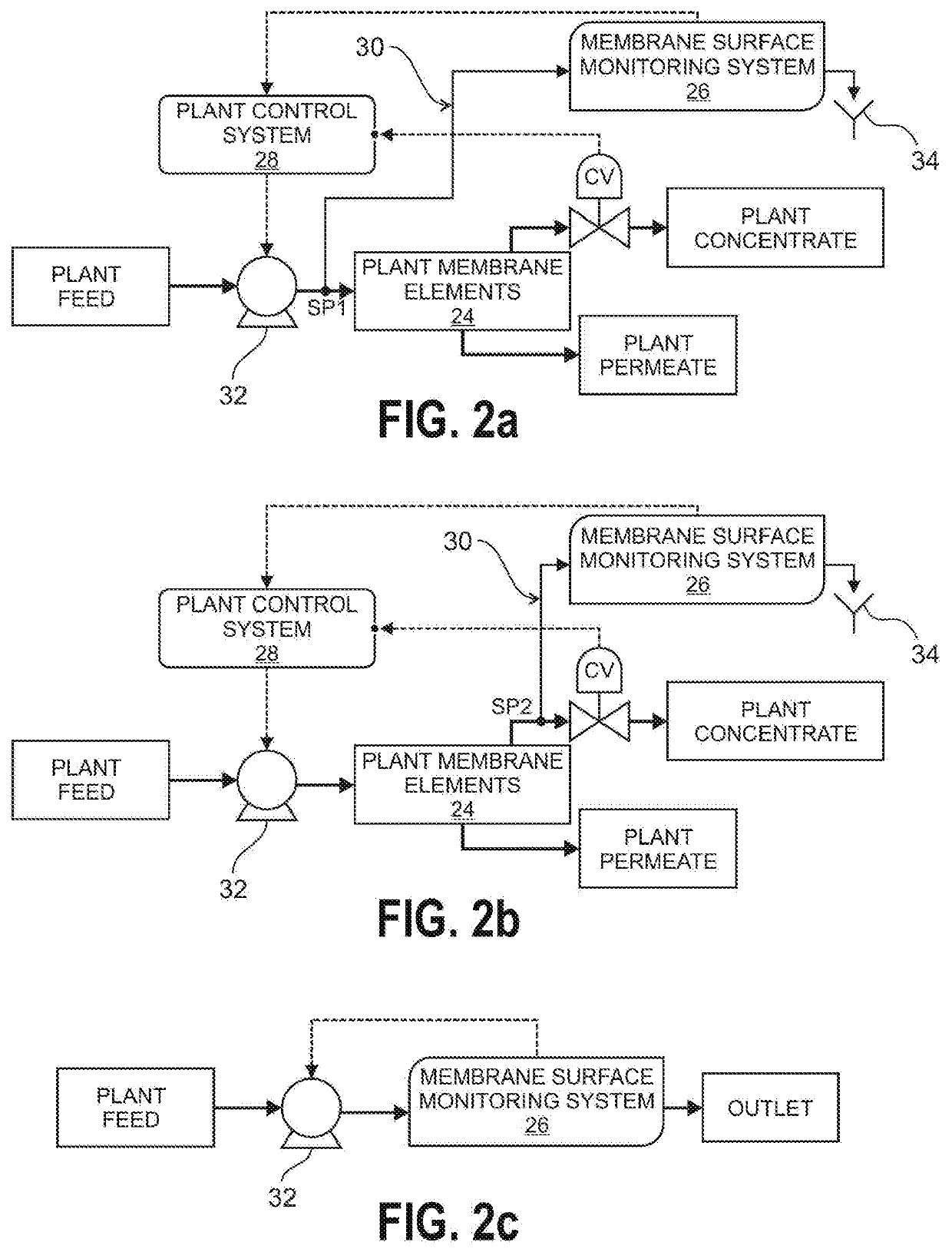
The invention is a system for monitoring the surface of membranes in real-time to detect and prevent scaling and fouling. The system uses an edge-lit light guide and an illuminated light source to capture images of the membrane surface, which are then analyzed to determine the type and severity of mineral scaling and fouling. This information is sent to a plant control system to trigger scale mitigation actions, adjust membrane operating pressure and feed flow rate, and perform other measures to keep the membrane surface clean and functioning properly. The system is automatic and can also be used for diagnostic purposes. It provides a more accurate and consistent way to monitor membrane surface quality and performance.

Problems solved by technology

However, the use of membranes is limited by membrane mineral scale formation on the membrane surface due to precipitation of sparingly water-soluble salts, as well as fouling by particulate, colloidal matter and biofoulants.
One problem in filtration systems and methods is that as product water recovery increases along the membrane modules, mineral concentrations of mineral salts increase near the membrane surface and in the bulk of the membrane channels' feed-side.
Mineral surface scaling results in permeate flux decline, which can ultimately lead to membrane damage and thus decreasing membrane longevity and increasing water treatment costs.
Membrane fouling due to particulate matter, organics and biofoulants (e.g., bacteria), also blocks the membrane surface, and thus reduce membrane performance.
Membrane mineral scaling and fouling both lead to flux reduction (for a given applied pressure) or demand increased applied pressure (for a given permeate flux) and thus result in increased operational (e.g., energy and treatment chemical) and maintenance costs.
It is noted that product water recovery may be limited even with the use of antiscalants.
Moreover, setting the precise antiscalant dose can be a challenge, particularly when there is variability in water feed quality and required water productivity.
Likewise, membrane fouling is affected by raw water feed quality, and feed pretreatment used to condition the raw feed water prior to membrane based water treatment / desalination.
These methods do not provide adequate early detection of scaling and fouling, and cannot be used to ascertain the type of scaling / fouling that occur.
However, these systems and methods have not sufficiently addressed the needs of the industry due to lack of sensitivity of the above approaches for early detection because they typically require a high surface loading of scalants or foulant deposits before affirmative scale detection can be made.
The above approaches also do not provide direct identification of the type of foulants or scalants on the membrane surface nor surface imaging of the membrane surface in either in an ex-situ membrane cell or directly of RO plant elements.
The latter approaches, however, are not suitable for membrane surface imaging when the fluid stream is under high pressure.
Moreover, such membrane surface imaging methods are impractical for real-time monitoring given the need for dye injection to provide optical contrast.
This attempted solution has not fully addressed the needs of the industry, owing to its awkwardness and fragility.
For example, one shortcoming of conventional systems using reflecting mirrors is the technical difficulty in producing 45-degree mirrors that are of the order of 1 mm and less in thickness.
Therefore, the use of mirrors is impractical when creating channels that mimic those found in commercial spiral-wound RO / NF elements, since channel height in such elements is typically less than 1 mm.
Another limitation in attempted solutions is the need for an optical window with multiple components needed to secure the optical window to the rest of the cell, and avoid leakage.
Irrespective of the above, creating a cell of height less than 1 mm would be infeasible due to the use of cell-embedded mirrors in conventional systems.
Still another deficiency of conventional systems is that membrane replacement requires dismantling of multiple components and repositioning of the light source after membrane replacement, and a retentate channel created by a rubber sheet that can age deform due to temperature changes over time and prolonged compression.

Method used


Image

  • Method and Apparatus for Real-Time Direct Membrane Monitoring
  • Method and Apparatus for Real-Time Direct Membrane Monitoring
  • Method and Apparatus for Real-Time Direct Membrane Monitoring

Examples


Embodiment Construction

[0035]The invention now will be described more fully hereinafter with reference to the accompanying drawings, in which embodiments of the invention are shown. This invention may however be embodied in many different forms and should not be construed as limited to the embodiments set forth herein. Rather, these embodiments are provided so that this disclosure will be thorough and complete, and will fully convey the scope of the invention to those skilled in the art.

[0036]It will be understood that when an element is referred to as being “on” another element, it can be directly on the other element or intervening elements may be present therebetween. As used herein, the term “and / or” includes any and all combinations of one or more of the associated listed items.

[0037]It will be understood that, although the terms first, second, third etc. may be used herein to describe various elements, components, regions, layers, and / or sections, these elements, components, regions, layers, and / or ...


PUM


Abstract

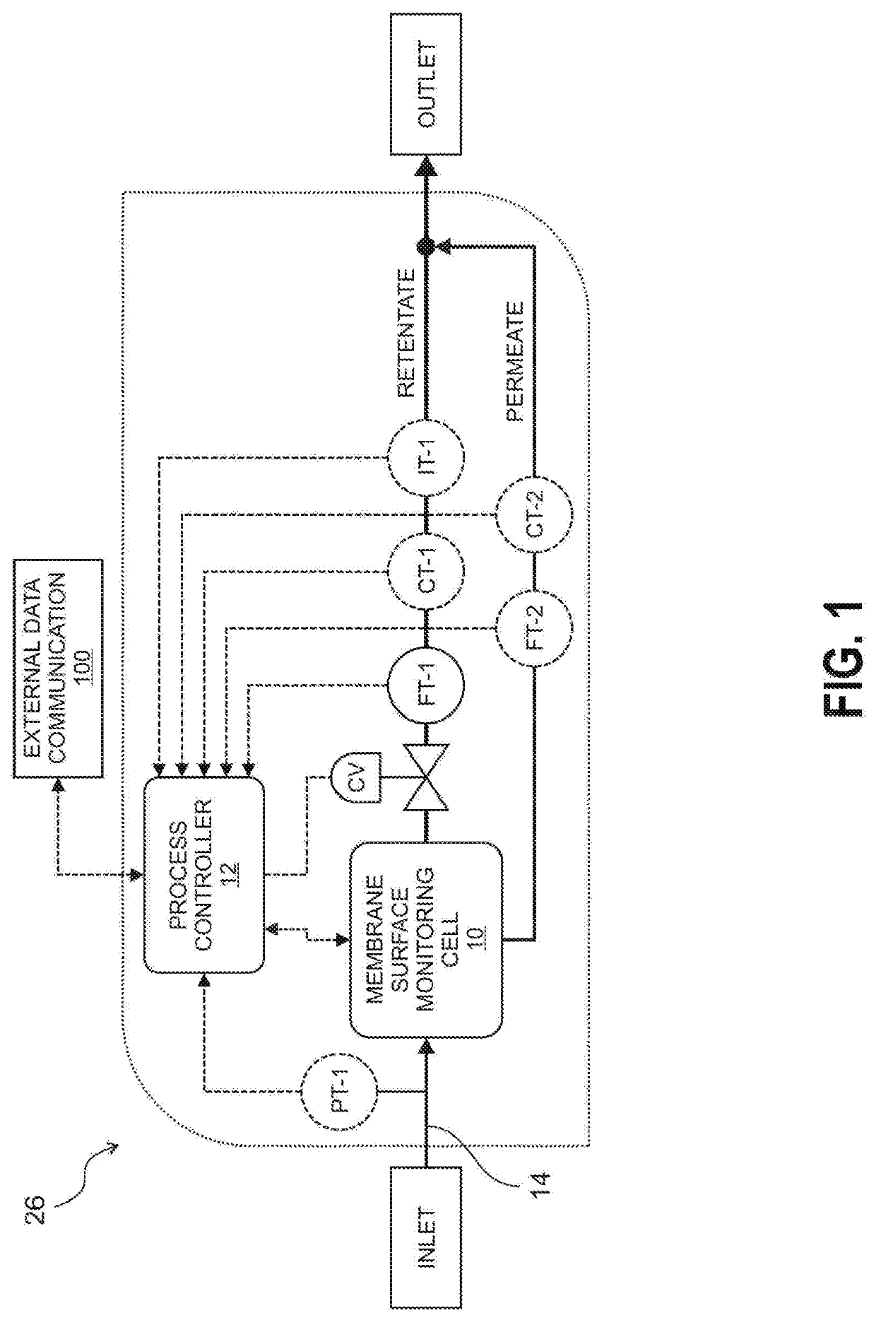
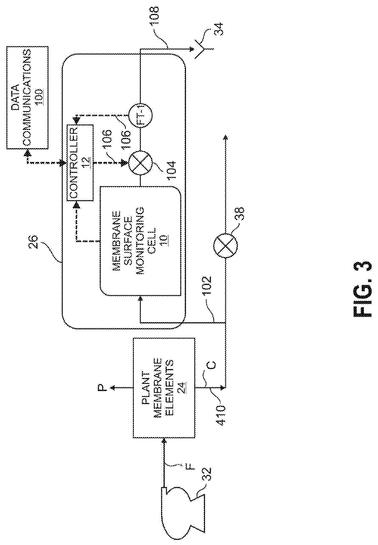
A membrane surface monitoring system (MSM) and membrane surface monitoring cell for direct and unambiguous detection of membrane surface fouling and mineral scaling. The system includes a membrane surface monitoring system cell, a control valve, a retentate flow meter / transmitter and a controller. The MSM cell has a visually-observable membrane, an edge-lit light guide, an edge illumination light source, a retentate module, and a permeate module. A pressurized inlet stream is fed into the MSM cell. The feed contacts a membrane sheet, leading to membrane-based separation operation to produce retentate and permeate streams. The MSM cell integrates surface illumination and imaging components to allow direct real-time visualization and spectral imaging of the membrane surface in real time. The pressure on the feed-side of the MSM cells is approximately that of the membrane plant element being monitored such that the plant control system can adjust plant operating conditions.

Description

CROSS-REFERENCE TO RELATED APPLICATIONS[0001]None.FEDERALLY SPONSORED RESEARCH OR DEVELOPMENT[0002]None.FIELD OF THE DISCLOSURE[0003]The present invention relates to a membrane surface monitoring (MSM) system, and more specifically to a MSM system for direct detection of membrane surface fouling and mineral scaling.BACKGROUND OF THE INVENTION[0004]Membrane technology is used for filtration of various liquids. This technology is particularly useful for water and wastewater treatment and water desalination as it is simple to operate, requires minimal chemical use, and produces consistent and reliable water quality.[0005]Some methods of filtration include the use of reverse osmosis (RO) and nanofiltration (NF), which can desalinate water by using a membrane. However, the use of membranes is limited by membrane mineral scale formation on the membrane surface due to precipitation of sparingly water-soluble salts, as well as fouling by particulate, colloidal matter and biofoulants.[0006]O...

Claims


Application Information

Patent Timeline
IPC IPC(8): B01D65/10G01N15/08B01D65/08H04N5/235
CPCG01N15/0806G01N2015/084B01D65/08B01D65/10G01N2015/0846H04N5/2354B01D61/12B01D2321/40Y02A20/131B01D2313/70B01D2313/903B01D2313/90H04N23/74B01D65/109
Inventor ANDITYA, RAHARDIANTOMUHAMMAD, BILAL
Owner NORIA WATER TECH INC
Learn More