
High-brightness luminescent yarn and manufacturing method thereof

Active Publication Date: 2020-11-05
CHANCE LINE IND
View PDF0 Cites 2 Cited by
  • Summary
  • Abstract
  • Description
  • Claims
  • Application Information

AI Technical Summary

Benefits of technology

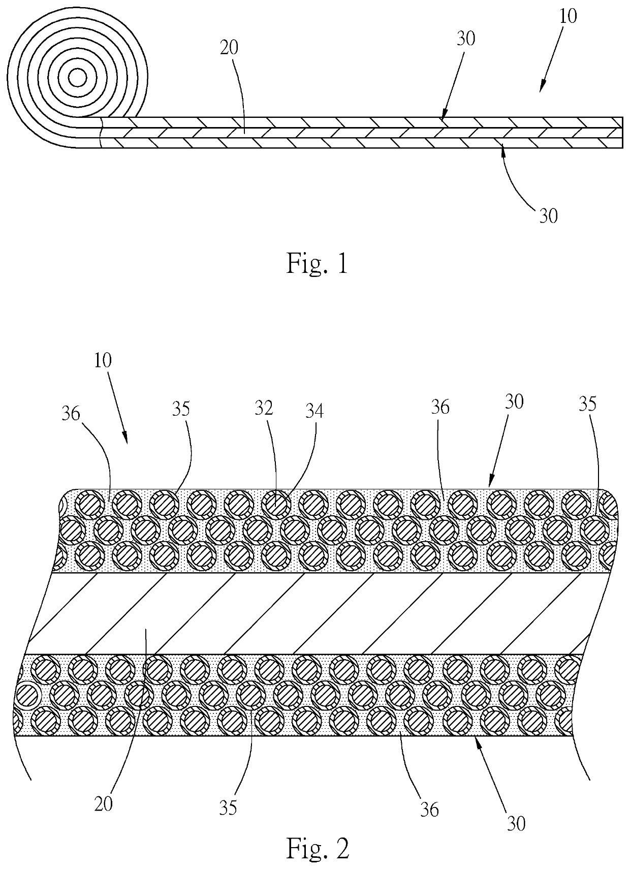
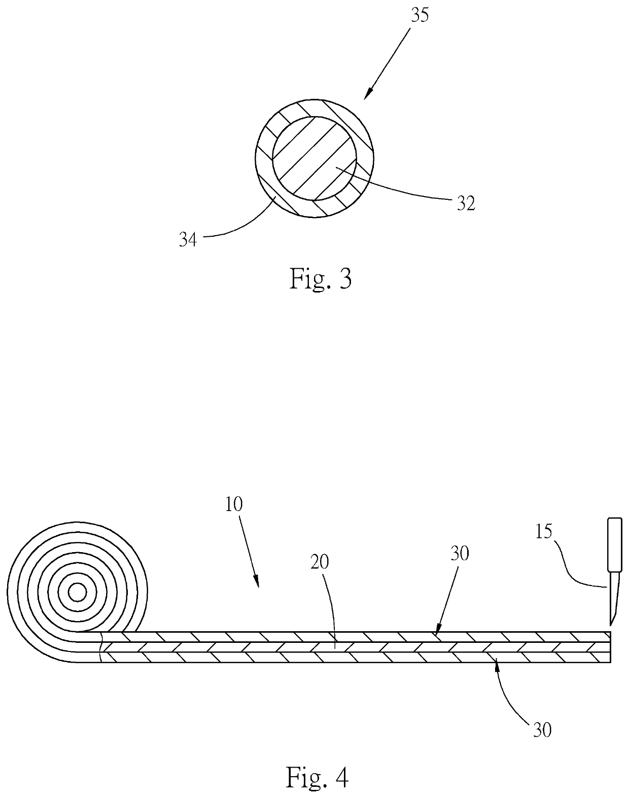
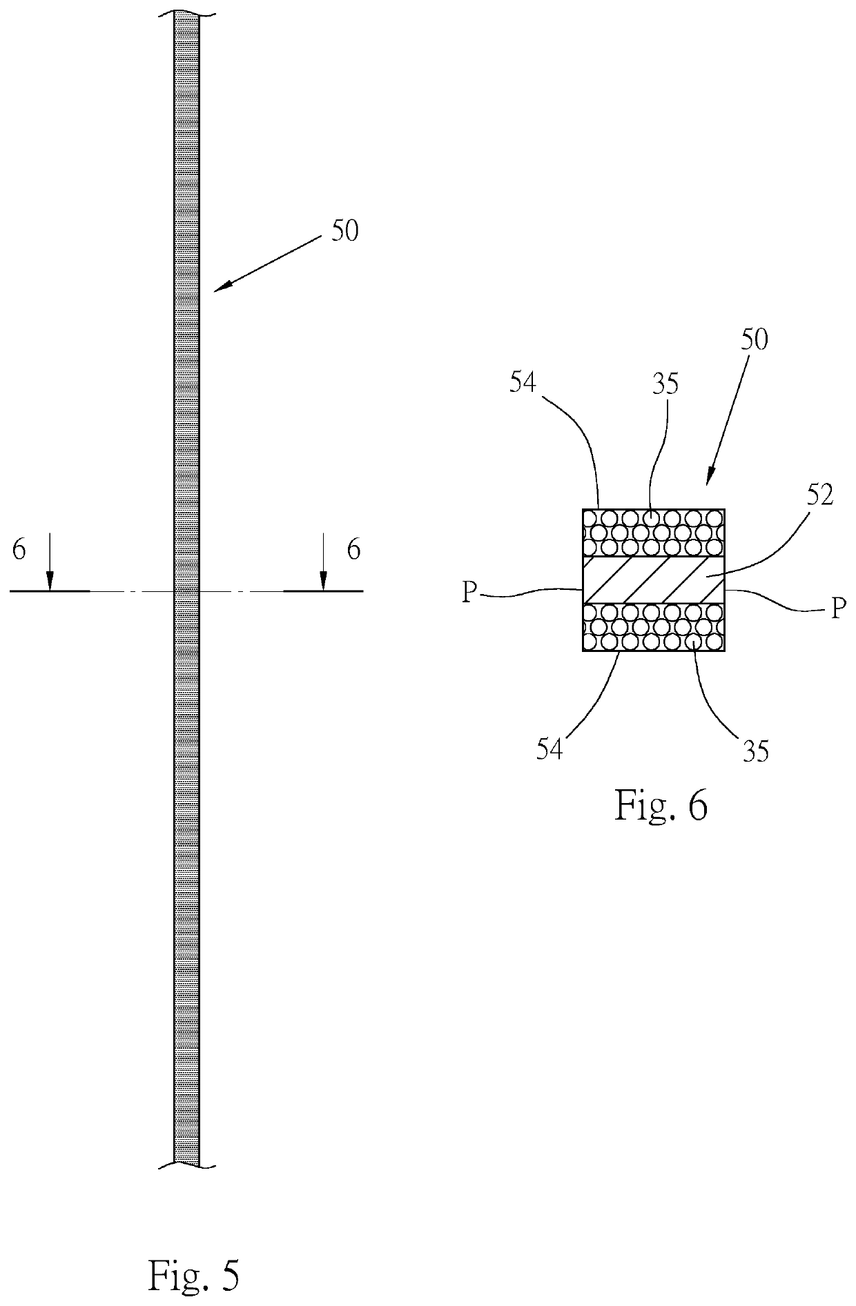
The present invention provides a new type of luminescent yarn with an improved structure and manufacturing method. The luminescent yarn emits light with higher brightness and has a longer lifetime. It also has higher strength. The luminescent particles are located on the surface of the yarn, which ensures better luminance and a longer lifespan without compromising the strength of the yarn. The luminescent surface layer has multiple microcapsule luminescent granules, which isolates the luminescent particles from outer side to ensure better protection and longer lifetime.

Problems solved by technology

Moreover, the light absorption efficiency is poor so that the light-emitting time is shortened.
Also, when the luminescent particles 74 emit light, the light is interrupted by the polyester so that the luminance of the light, (that is, the brightness of the luminescence) is poor.
The luminescent particles 74 are distributed in the main body 72, this results in deterioration of the strength of the main body so that the strength of the conventional luminescent yarn 70 is poor and the conventional luminescent yarn 70 cannot bear greater tension and is apt to be pulled and broken apart by the weaving machine.
Therefore, in the conventional drawnwork manufacturing method, the yarn-drawing die head of the yarn-drawing machine will be worn by the luminescent particles so that the manufacturing cost for the luminescent yarn is higher.
Such dyeing manufacturing method can diversify the appearance color of the luminescent yarn, however, the dye will infiltrate into the luminescent particles to deteriorate the light absorption efficiency of the luminescent particles so that the light absorption efficiency of the luminescent powders will become poorer.
In addition, the dye will interrupt the luminescence emitted from the luminescent particles at night.
Therefore, the luminescence of the current colored luminescent yarn has poor brightness and short light-emitting time.
Also, the luminescence will decay quickly so that the luminescent efficiency is poor.

Method used


Image

  • High-brightness luminescent yarn and manufacturing method thereof
  • High-brightness luminescent yarn and manufacturing method thereof
  • High-brightness luminescent yarn and manufacturing method thereof

Examples


second embodiment

[0053]FIG. 9 is a sectional view showing the luminescent yarn 50′ of the present invention. The film material for cutting into the luminescent yarn 50′ has a substrate material and a luminescent layer. Therefore, the luminescent yarn 50′ is a two-layer structure with a cross-section in the form of a rectangle. The cross-section of the luminescent yarn 50′ has a main body 52 and a luminescent surface layer 54 positioned on a surface of the main body 52. The main body 52 has transparence so that the luminescent surface layer 54 can emit luminescence through the other surface of the main body 52, whereby both surfaces of the luminescent yarn 50′ can provide luminescent effect.

[0054]In the above content, the color of the luminescent yarn is not changed. According to the technical content of the present invention, the luminescent yarn can be made with different appearance colors so that the luminescent yarn can present various colors in daytime or a bright place. The appearance color is ...

third embodiment

[0055]FIG. 10 is a sectional view showing the film material 10′ of the present invention. The film material 10′ also includes a substrate material 20′ and two luminescent layers 30 coated on two surfaces of the substrate material, wherein a dye (color) or paint is added into the substrate material 20′ so that the substrate material 20′ has different colors. For example, the dye is filled into the substrate material or a calender is used to calender the dye and the substrate material to uniformly blend the dye with the substrate material, whereby the substrate material has the color of the dye. Accordingly, the color of the substrate material 20′ is changed to further manufacture the luminescent yarn with different colors. The three layers of films of the film material 10′ can be made by means of attachment. Alternatively, the three layers of films of the film material 10′ can be coated on a carrier body by means of the second manufacturing method as shown in FIG. 8, (in which the fi...

fourth embodiment

[0056]FIG. 11 is a sectional view showing the film material 10″ of the present invention. The film material 10″ includes a substrate material 20, two colored layers 22 and two luminescent layers 30. The two colored layers 22 are polymer material films respectively disposed on two surfaces of the substrate 20 by means of printing, coating (including coating on the carrier body) or attachment. The two luminescent layers 30 are respectively disposed on outer surfaces of the two colored layers 22 by means of coating (including coating on the carrier body) or attachment. When manufacturing the film material 10″, the colored layers 22 with desired color can be selectively used, whereby the color of the two colored layers 22 becomes the color of the film material 10″. That is, in this embodiment, by means of the colored layers 22, the color of the substrate material and the film material is changed. The two colored layers 22 can be made with various colors as necessary. Alternatively, the ...


PUM

PropertyMeasurementUnit
Coloraaaaaaaaaa
Flexibilityaaaaaaaaaa
Transparencyaaaaaaaaaa

Abstract

A luminescent yarn and a manufacturing method thereof. The luminescent yarn is a multilayered structure, a cross-section of the yarn includes a main body and at least one luminescent surface layer having multiple luminescent particles and positioned on at least one surface of the main body. Accordingly, the luminescent surface layer is positioned on the surface of the luminescent yarn to directly absorb energy and emit luminescence, whereby the luminescent yarn has better luminance and longer luminescence-emitting time. The manufacturing method of the luminescent yarn includes steps of: manufacturing a film material, the film material having a substrate material and at least one luminescent layer disposed on at least one surface of the substrate material; and cutting the film material to form the luminescent yarn.

Description

BACKGROUND OF THE INVENTION1. Field of the Invention[0001]The present invention relates generally to a luminescent article, and more particularly to a luminescent yarn and a manufacturing method thereof.2. Description of the Related Art[0002]A luminescent yarn can emit luminescence at night. After the luminescent powders of the yarn absorb light, the luminescent powders will emit light in a dark place. The luminescent yarns can be woven into a fabric to manufacture a clothes. The clothes made of the luminescent yarns can emit luminescence at night to enhance the safety in activity at night.[0003]FIG. 16 is a schematic view of a conventional luminescent yarn 70. The luminescent yarn 70 is made of a mixture of luminescent powders and polyester by means of drawnwork. The polyester forms the main body 72 of the luminescent yarn 70. The luminescent powders are formed of fine luminescent particles 74 distributed in the main body 72. A single-filament or a multi-filament luminescent yarn c...

Claims


Application Information

Patent Timeline
IPC IPC(8): D02G3/36D02G3/02
CPCD02G3/02D02G3/36D02G3/34C09K11/02D01F1/04D01F1/06D02G3/441D02G3/06
Inventor YAO, MING-HSIEN
Owner CHANCE LINE IND
Learn More