
Multimode waveguide grating coupler

a waveguide and coupler technology, applied in the direction of optical waveguide light guides, instruments, optical elements, etc., can solve problems such as limited performance, and achieve the effect of increasing the communication bandwidth of optical fibers

Active Publication Date: 2020-10-22
THE CHINESE UNIVERSITY OF HONG KONG
View PDF0 Cites 6 Cited by
  • Summary
  • Abstract
  • Description
  • Claims
  • Application Information

AI Technical Summary

Benefits of technology

The patent text discusses a way to increase the bandwidth of optical communication by using multiple modes in an optical fiber. This is done using a special coupler that can connect different modes of a fiber. By doing this, more information can be transmitted over the fiber, improving communication speed and bandwidth.

Problems solved by technology

However, due to severe mode mismatch and limited directionality, the previous attempts of using waveguide grating couplers to launch light into multimode optical fibers have limited performance with typical experimental coupling efficiency reported to be less than −20 dB.

Method used


Image

  • Multimode waveguide grating coupler
  • Multimode waveguide grating coupler
  • Multimode waveguide grating coupler

Examples


example process

VI. EXAMPLE PROCESS

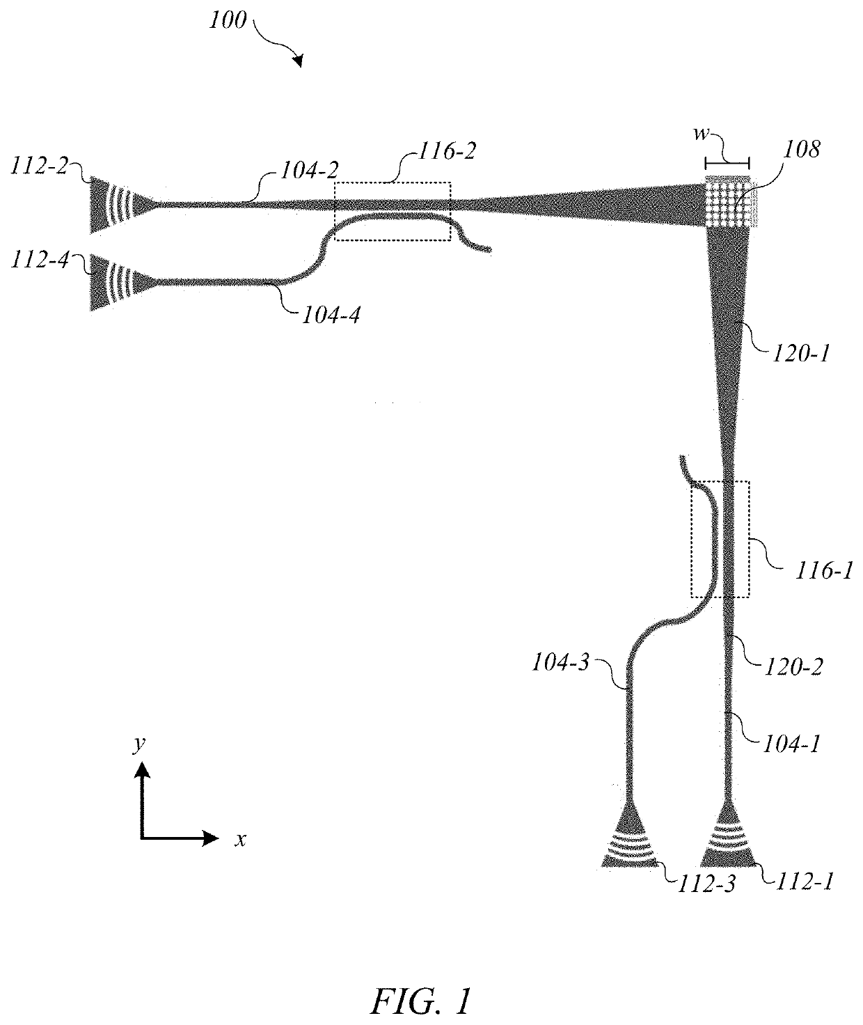
[0083]FIG. 11 depicts an embodiment of a flowchart of a method 1100 for spatial multiplexing. Method 1100 starts in step 1104 with coupling a first optical beam into a first waveguide. The first optical beam can be coupled into the first waveguide so that the first optical beam propagates in a fundamental mode of the first waveguide. For example, a first signal is coupled into the first waveguide 104-1 through the first input 112-1 in FIG. 1.

[0084]In step 1108, a second optical beam is coupled into a second waveguide. The second optical beam can be coupled into the second waveguide so that the second optical beam propagates in a fundamental mode of the second waveguide. For example, a second signal is coupled into the second waveguide 104-2 through the second input 112-2 in FIG. 1. The second waveguide is orthogonal to the first waveguide.

[0085]In step 1112, a third optical beam is coupled into the first waveguide. A first asymmetric directional coupler can be use...


PUM

PropertyMeasurementUnit
widthaaaaaaaaaa
widthaaaaaaaaaa
diameteraaaaaaaaaa

Abstract

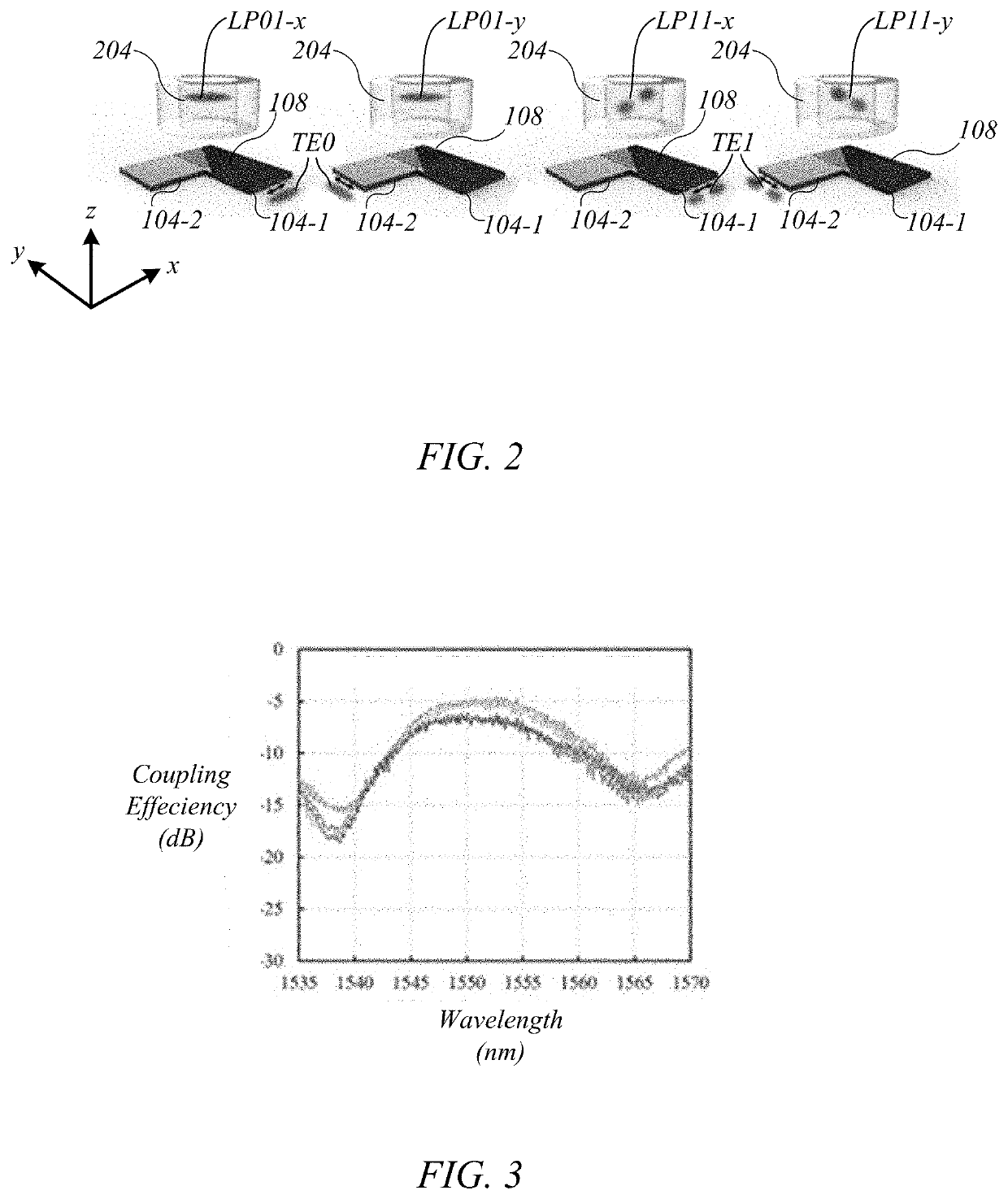
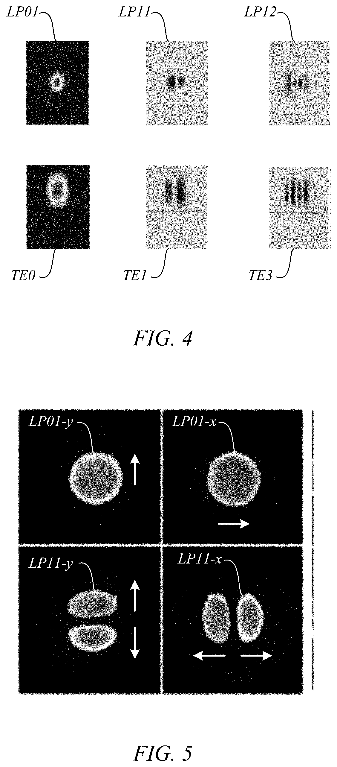
We describe a high coupling-efficiency waveguide grating coupler for use in the optical interface between a planar multimode waveguide and a multimode optical fiber in mode division multiplexed optical communication systems. The multimode waveguide grating coupler can launch light from the different modes of the planar waveguide into the different modes of the multimode optical fiber and vice-versa. A silicon based multimode waveguide grating coupler was used to couple two polarizations of a multimode silicon waveguide into the LP01 mode and LP11 mode from a step index multi-mode fiber (MMFs). Simulations of the preliminary design predicted the coupling efficiency to be −4.3 dB for LP01 mode and −5.0 dB for the LP11 mode. Experimental coupling efficiency of −4.9 dB and −6.1 dB were obtained for LP01 and LP11, respectively. The multiplexer can be passive.

Description

CROSS REFERENCE TO RELATED APPLICATIONS[0001]This application claims priority to U.S. Provisional Application No. 62 / 837,042, filed on Apr. 22, 2019, the disclosure of which is incorporated by reference in its entirety for all purposes.BACKGROUND OF THE INVENTION[0002]Optical communication uses light to convey information. Data centers and communication across the Internet rely heavily on optical-fiber communication.[0003]In 2012, Ryf demonstrated the use of mode division multiplexing in multimode optical fibers by using an arrangement of beam splitters, mirror phase plates (spatial light modulators) and lenses to couple light from six single-mode fibers into a multimode fiber. R. Ryf et al., “Mode-Division Multiplexing Over 96 km of Few-Mode Fiber Using Coherent 6×6 MIMO Processing,” Journal of Lightwave Technology, vol. 30, no. 4, pp. 521-531, February 2012. The theoretical best coupling efficiency for launching into the LP01 and LP11 modes of the fiber was reported to be −5.5 dB,...

Claims


Application Information

Patent Timeline
Patent Type & Authority Applications(United States)
IPC IPC(8): G02B6/34H04B10/27H04B10/25
CPCH04B10/27H04B10/25G02B6/34H04J14/04G02B6/1228G02B6/14G02B6/30G02B6/124H04B10/2581
Inventor TSANG, HON KITONG, YEYU
Owner THE CHINESE UNIVERSITY OF HONG KONG
Learn More