
Electronic device for determining the angular position of a motor vehicle shaft

a technology for motor vehicles and angular positions, applied in the field of position sensors, can solve the problems of significant drawbacks of complex printed circuit boards on which free space is limited, time-consuming and expensive welding operations necessary to fasten the tabs of the guide, and significant temperature increase on the electronic circui

Active Publication Date: 2020-10-22
CONTINENTAL AUTOMOTIVE FRANCE +1
View PDF6 Cites 0 Cited by
  • Summary
  • Abstract
  • Description
  • Claims
  • Application Information

AI Technical Summary

Benefits of technology

The present invention proposes a simple, reliable and effective solution for fastening a magnetic guide to a printed circuit board. The device allows for easy adhesive fastening with optimal strength of the bond between the adhesive and the pad on the printed circuit board. This method does not require any welding, which helps to avoid heating and release of gas that could limit the effectiveness of the adhesive bonding. The pad has a cylindrical surface that increases the contact surface with the adhesive. The adhesive used is an acrylate base that is flexible and resistant to thermal shocks.

Problems solved by technology

However, fastening the guide to the printed circuit board in this way exhibits drawbacks because it is necessary to provide orifices that may prove to be bulky, thereby exhibiting a significant drawback for a complex printed circuit board on which free space is limited.
In addition, creating such orifices and the welding operations necessary to fasten the tabs of the guide may prove time-consuming and expensive.
Lastly, the welding operation may lead to a significant increase in temperature on the electronic circuit, which may damage it, and therefore exhibits a major drawback.

Method used


Image

  • Electronic device for determining the angular position of a motor vehicle shaft
  • Electronic device for determining the angular position of a motor vehicle shaft
  • Electronic device for determining the angular position of a motor vehicle shaft

Examples


first embodiment

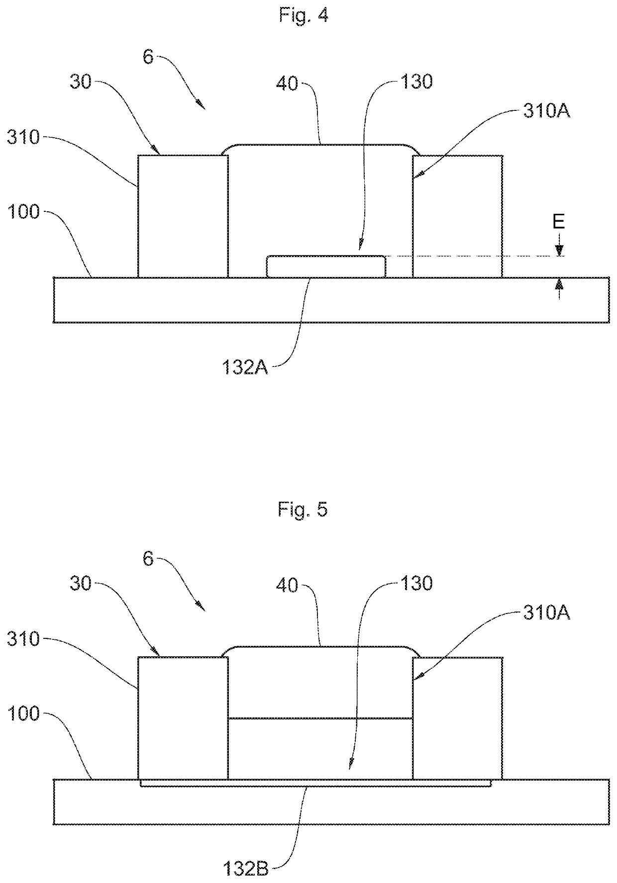
[0074]According to a first embodiment of a fastening area 130 illustrated in FIG. 4, the pad 132A has a diameter less than 1.5 mm. In other words, the pad 132A has a diameter smaller than that of the fastening area 130. Part of the base substrate 100 is thus covered neither by the pad 132A nor by the protective varnish 120 in the fastening area 130.

[0075]The adhesive 40 thus adheres both to the pad 132A and to the uncovered base substrate 100, thereby making it possible to optimize the strength of the adhesive bonding of the magnetic guide 30 to the printed circuit board 10.

[0076]The pad 132A has a height E less than 0.15 mm, preferably of the order of 120 micrometers. Such a thickness of the pad 132A thus makes it possible to define a cylindrical surface of the pad 132A to which the adhesive 40 adheres, increasing the contact surface between the pad 132A and the adhesive 40, thereby making it possible to further increase the strength of the adhesive bonding of the magnetic guide 30...

second embodiment

[0077]According to a second embodiment of a fastening area 130 illustrated in FIG. 5, the pad 132B has a diameter greater than or equal to 2.5 mm, preferably of the order of 4 mm. Such a pad 132B thus covers the entire surface of the base substrate 100 that is not covered with protective varnish 120.

[0078]Such a pad 132B thus makes it possible to maximize the contact surface between the pad 132B and the adhesive 40 in order to increase the mechanical strength of such adhesive bonding.

[0079]According to one aspect of the invention, the pad 132B is contained within the thickness of the base substrate 100. In other words, the pad 132B does not project from the base substrate 100.

[0080]Implementation of the Invention

[0081]A description will now be given of the method for manufacturing a fastening area 130.

[0082]First of all, a pad 132A, 132B is placed on the base substrate 100 in each fastening area 130. Such a pad 132A initially has a greater thickness, preferably greater than 150 micr...


PUM


Abstract

Disclosed is an electronic device for determining the angular position of a shaft of a motor vehicle, the device including a printed circuit board and a magnetic guide including at least two fastening tabs for fastening to the printed circuit board, the printed circuit board including a base substrate and at least two fastening areas for fastening the magnetic guide, each designed to receive a fastening tab of the magnetic guide, the fastening tab defining a fastening orifice. Each fastening area is defined on the base substrate of the printed circuit board and includes a pad fastened to the base substrate. Each fastening tab is joined to the pad of the corresponding fastening area by way of an adhesive that is applied in its fastening orifice.

Description

BACKGROUND OF THE INVENTIONField of the Invention[0001]The present invention pertains to the field of position sensors and relates more particularly to an electronic device for determining the angular position of a shaft of a vehicle.[0002]The invention is particularly applicable to determining the angular position of a shaft of a power steering system of a motor vehicle.Description of the Related Art[0003]A motor vehicle comprises, as is known, a power steering system for multiplying the force provided by the driver on the steering wheel. The driver is thus able to turn the wheels, in particular at a low speed of the vehicle, by providing a limited force.[0004]Hydraulic power steering systems are known, but they are increasingly often being replaced with electrical systems in order to limit their costs and their bulk.[0005]An electrical power steering system, as is known, comprises an electric motor driving a shaft in rotation in order to control the pivoting of the wheels. It is k...

Claims


Application Information

Patent Timeline
IPC IPC(8): B62D5/04G01D5/14B62D15/02
CPCB62D5/046B62D15/0235G01D5/14B62D15/0215G01L5/221G01R33/038H05K1/181H05K3/305H05K3/3426H05K3/4015H05K9/0028H05K2201/10151H05K2201/10242H05K2201/1025H05K2201/10371Y02P70/50
Inventor COUARRAZE, STÉPHANE
Owner CONTINENTAL AUTOMOTIVE FRANCE
Learn More