
Single-Shell Spring Control Arm

a spring control arm and single-shell technology, applied in the direction of resilient suspensions, vehicle springs, vehicle components, etc., can solve the problems of increased material costs, increased weight per spring control arm, and insufficient rigidity of spring control arms, so as to improve the stiffness of relatively lightweight spring control arms, reduce manufacturing costs, and optimize the effect of spring control arms

Active Publication Date: 2020-10-15
AUTOTECH ENG DEUT
View PDF0 Cites 10 Cited by
  • Summary
  • Abstract
  • Description
  • Claims
  • Application Information

AI Technical Summary

Benefits of technology

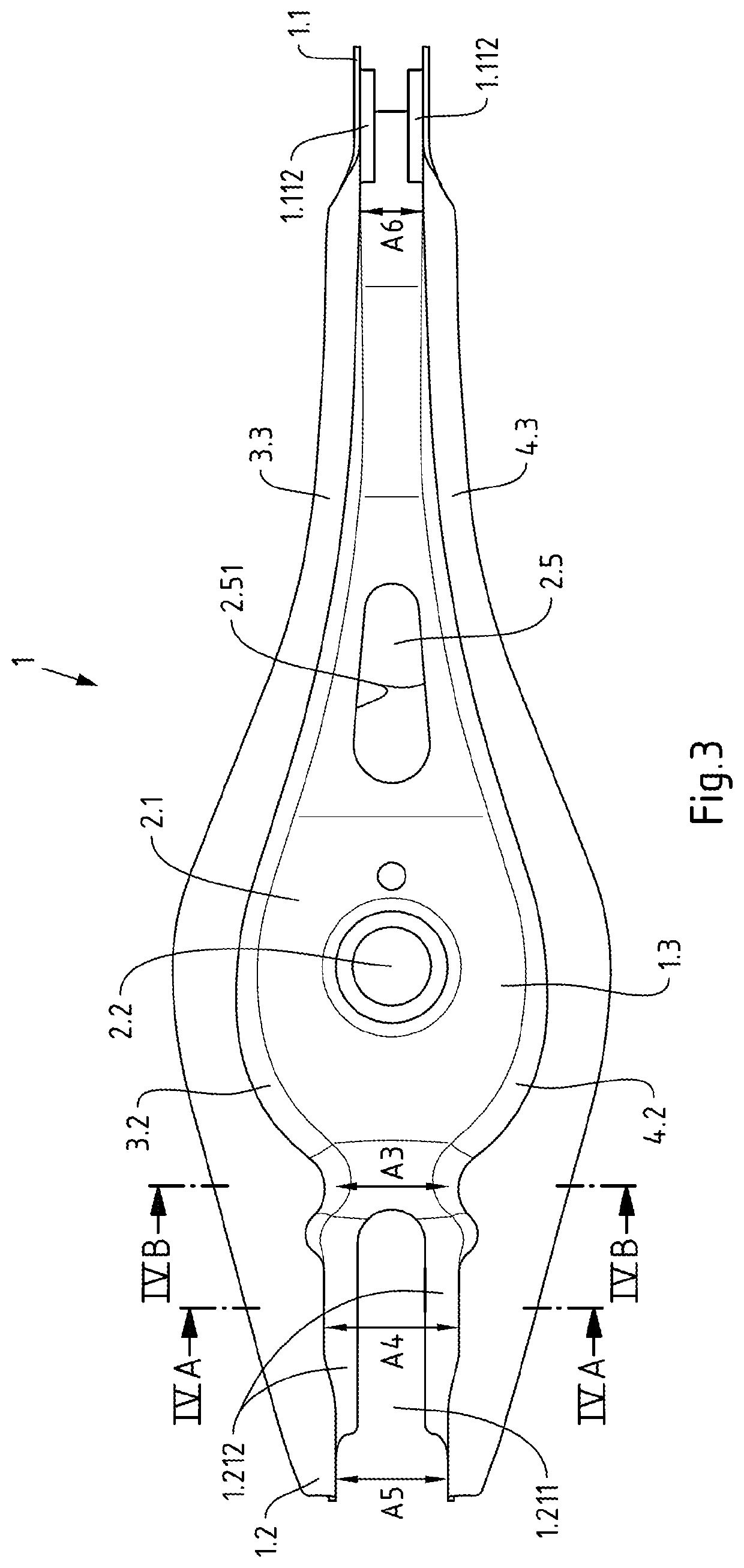
The U-shaped constriction of the spring control arm allows for improved stiffness when dealing with high axle loads. This design does not require additional metal sheets or increased material thickness, making it a lightweight and cost-effective solution. Additionally, an elongated opening is formed in the base of the spring control arm, which serves to connect it to a chassis girder. This opening is significantly longer than any other measurement on the control arm, reducing its weight. The edges of this opening run diverging from each other, increasing in distance towards the spring support surface. This design helps further reduce the weight of the spring control arm.

Problems solved by technology

However, it has been shown that the spring control arm is not sufficiently rigid at the damper connection between the wheel-side connection and the spring support surface when used in similar motor vehicles with electric drive, where a significantly higher axle load occurs due to the high weight of the drive accumulator, and that it sometimes fails.
However, an increase in material thickness leads to a considerable increase in weight per spring control arm and higher material costs.
However, the manufacture of such additional metal sheets requires corresponding manufacturing steps, which is unfavourable with regard to the manufacturing costs.
In addition, well-known multi-part spring control arms sometimes have a relatively high component weight due to their reinforcing additional metal sheets.

Method used


Image

  • Single-Shell Spring Control Arm
  • Single-Shell Spring Control Arm
  • Single-Shell Spring Control Arm

Examples


Embodiment Construction

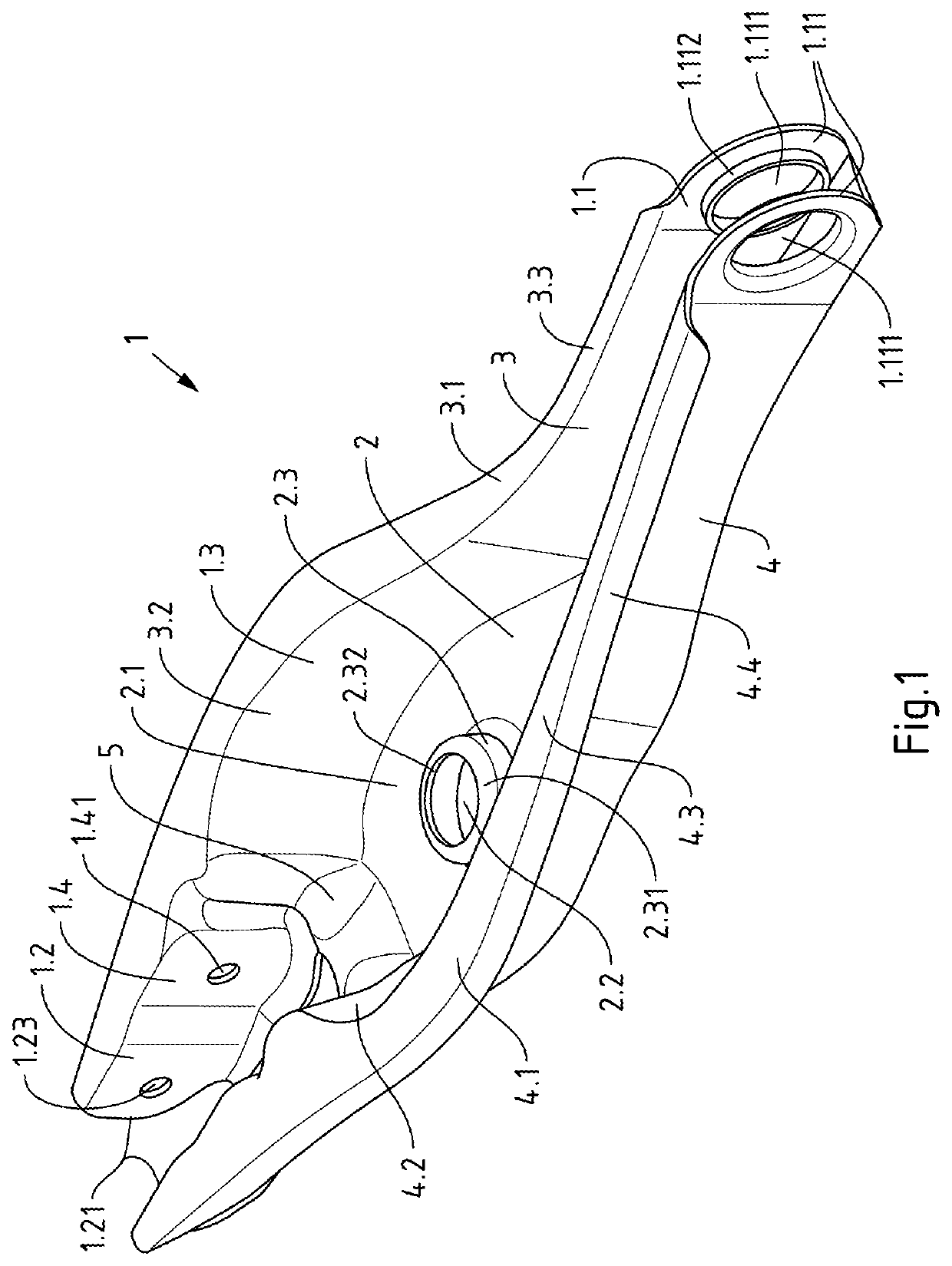
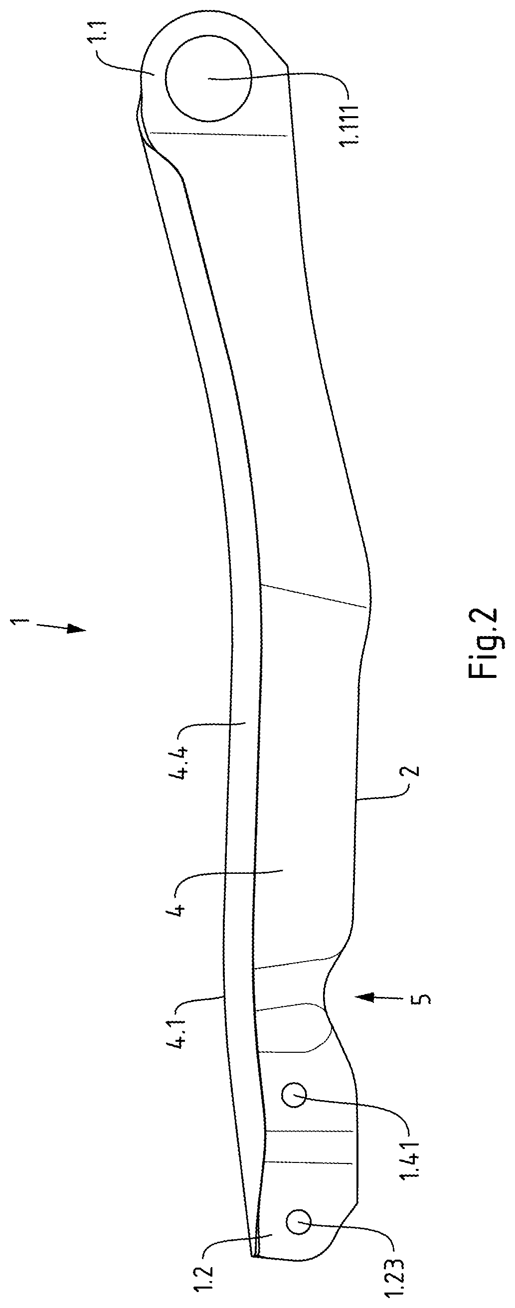
[0036]The drawing shows a spring control arm 1 for a wheel suspension of a motor vehicle. The spring control arm 1 has upwardly directed side limbs 3, 4 connected by a base 2 and is manufactured as a single-shell component from a metal plate by punching and forming. It has a first end section 1.1 for connection to a chassis girder and a second end section 1.2 for connection on the wheel side. Between the two end sections 1.1, 1.2 there is a spring receiving section 1.3 which has a spring support surface 2.1 formed on the base 2 for supporting a spring (helical spring) (not shown here). Furthermore, the spring control arm 1 has a damper receiving section 1.4 between the spring receiving section 1.3 and the second end section 1.2 for connecting a shock absorber (not shown here).

[0037]The spring control arm 1 is made of high-strength sheet metal, preferably high-strength sheet steel. The metal sheet or steel sheet used for its manufacture has a yield strength of at least 600 MPa, prefe...


PUM


Abstract

The invention relates to a single-shell spring control arm formed of sheet metal for a wheel suspension of a motor vehicle, with upwardly directed side limbs connected to one another by a base, with a first end section for connection to a chassis girder, with a second end section for wheel-side connection, with a spring receiving section, which is located between the two end sections and has a spring support surface formed on the base, and with a damper receiving section formed between the spring receiving section and the second end section for connecting a shock absorber. In order to achieve at relatively low component weight and favorable manufacturing costs improved stiffness with respect to high axle loads, the invention provides that a U-shaped constriction is formed between the spring support surface and the damper receiving section, which constriction extends in the base and in the side limbs.

Description

CROSS-REFERENCE TO RELATED APPLICATION[0001]This application claims priority to European Patent Application No. 19168696.3 filed Apr. 11, 2019, the disclosure of which is hereby incorporated by reference in its entirety.BACKGROUND OF THE INVENTIONField of the Invention[0002]The invention relates to a single-shell spring control arm formed of sheet metal for a wheel suspension of a motor vehicle, with upwardly directed side limbs connected to one another by a base, with a first end section for connection to a chassis girder, with a second end section for wheel-side connection, with a spring receiving section, which is located between the two end sections and has a spring support surface formed on the base, and with a damper receiving section formed between the spring receiving section and the second end section for connecting a shock absorber.Description of Related Art[0003]Spring control arms serve to guide a chassis wheel on a wheel suspension of a motor vehicle. They have a sectio...

Claims


Application Information

Patent Timeline
Patent Type & Authority Applications(United States)
IPC IPC(8): B60G7/00B60G7/02B60G13/00
CPCB60G2204/1244B60G2204/148B60G13/005B60G7/008B60G2204/129B60G2204/143B60G7/02B60G7/001B60G11/16B60G2206/722B60G2206/10B60G2202/12B60G2206/141B60G2206/16
Inventor FRENZEL, OLIVERNIEMANN, JULIAN
Owner AUTOTECH ENG DEUT
Learn More