
Heatsink retainer assembly

a technology for retaining devices and heatsinks, which is applied in the direction of cooling/ventilation/heating modifications, semiconductor device details, semiconductor/solid-state device details, etc., can solve the problems of small end fittings, small and difficult assembly, and interference with the end of the anchorage, so as to reduce the difficulty of assembly, the effect of compromising the fit or function of the wir

Active Publication Date: 2020-10-01
RADIAN THERMAL PROD
View PDF0 Cites 0 Cited by
  • Summary
  • Abstract
  • Description
  • Claims
  • Application Information

AI Technical Summary

Benefits of technology

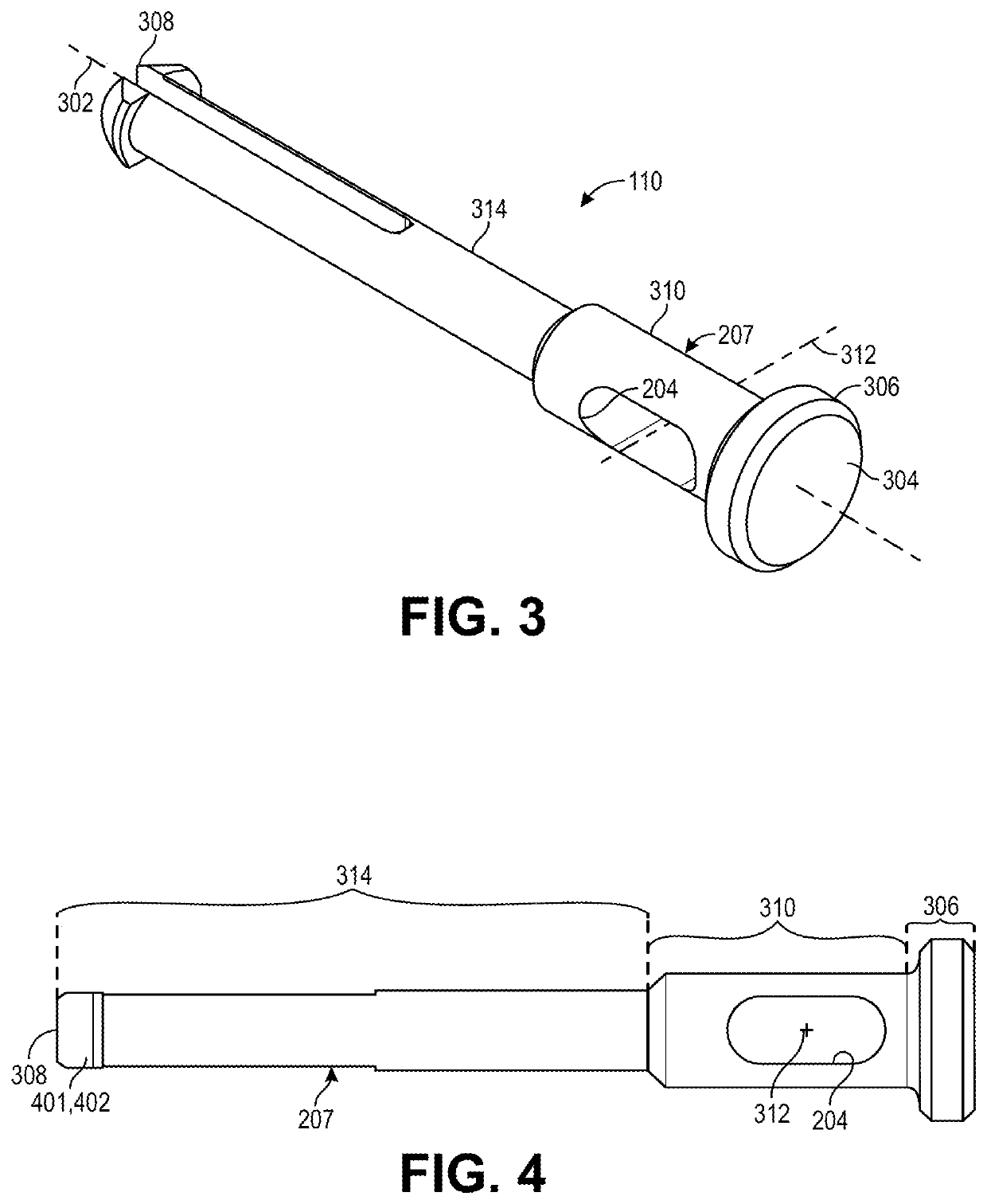
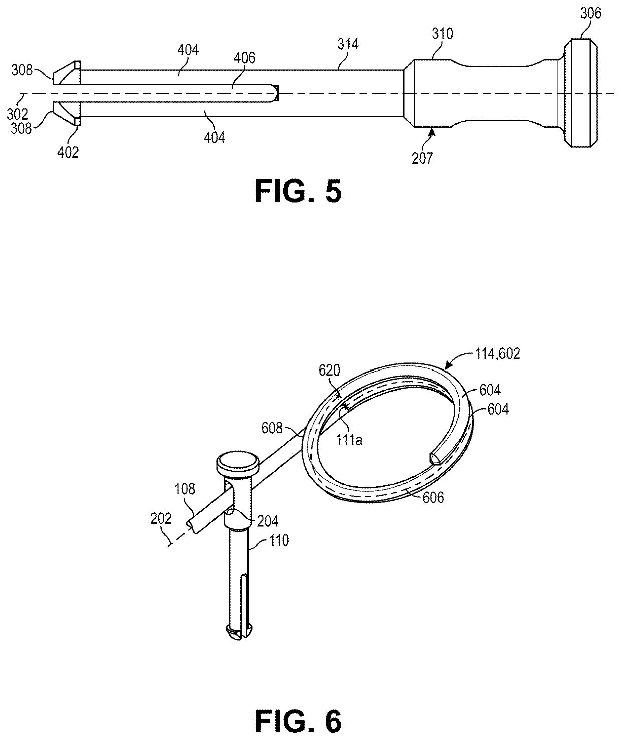
The heatsink retainer assembly described in this patent allows for easy assembly and positioning of the anchor, which is a component of the heatsink retainer assembly. The anchor can slide along the retention wire, making it easy to move and position in the carrier substrate. The pin portion of the anchor has prongs that can collapse radially to grip the bottom side of the carrier substrate and resist backout of the anchor. The assembly is less likely to be fumbled, lost, or inadvertently ejected into a face of an assembler. Overall, this heatsink retainer assembly provides a more secure and efficient way to keep the heatsinking process organized and efficient.

Problems solved by technology

The retention feature interferes with the end of the anchor to fasten the wire to the anchor.
Existing retention hardware includes numerous parts that are small and difficult to assemble.
The anchor components are small, loose parts that can be fumbled or lost.
Similarly, the end fittings are small and have retention features that require care and time to manually engage the ends of the anchors.
Thus, not only are the individual components difficult to handle alone, but their size also complicates the act of attaching the components to each other.
Notably, the difficulty in securing the end fittings to the anchors can create a hazard because the wire is placed under tension during installation, and if the end fitting-to-anchor attachment fails, or slips from the grip of the assembler or a tool used by the assembler, the wire can eject into a face of the assembler.
An assembler may attempt to bend the wire of the retention hardware to correct for any misalignment of the anchor, and in such case, the fit or function of the wire may be compromised.
Additionally, any misalignment such as may result from design inaccuracy or manufacturing tolerance can exert a lateral load on the heatsink that misaligns the heatsink with the electronic component, resulting in degraded heatsink performance.

Method used


Image

  • Heatsink retainer assembly
  • Heatsink retainer assembly
  • Heatsink retainer assembly

Examples


Embodiment Construction

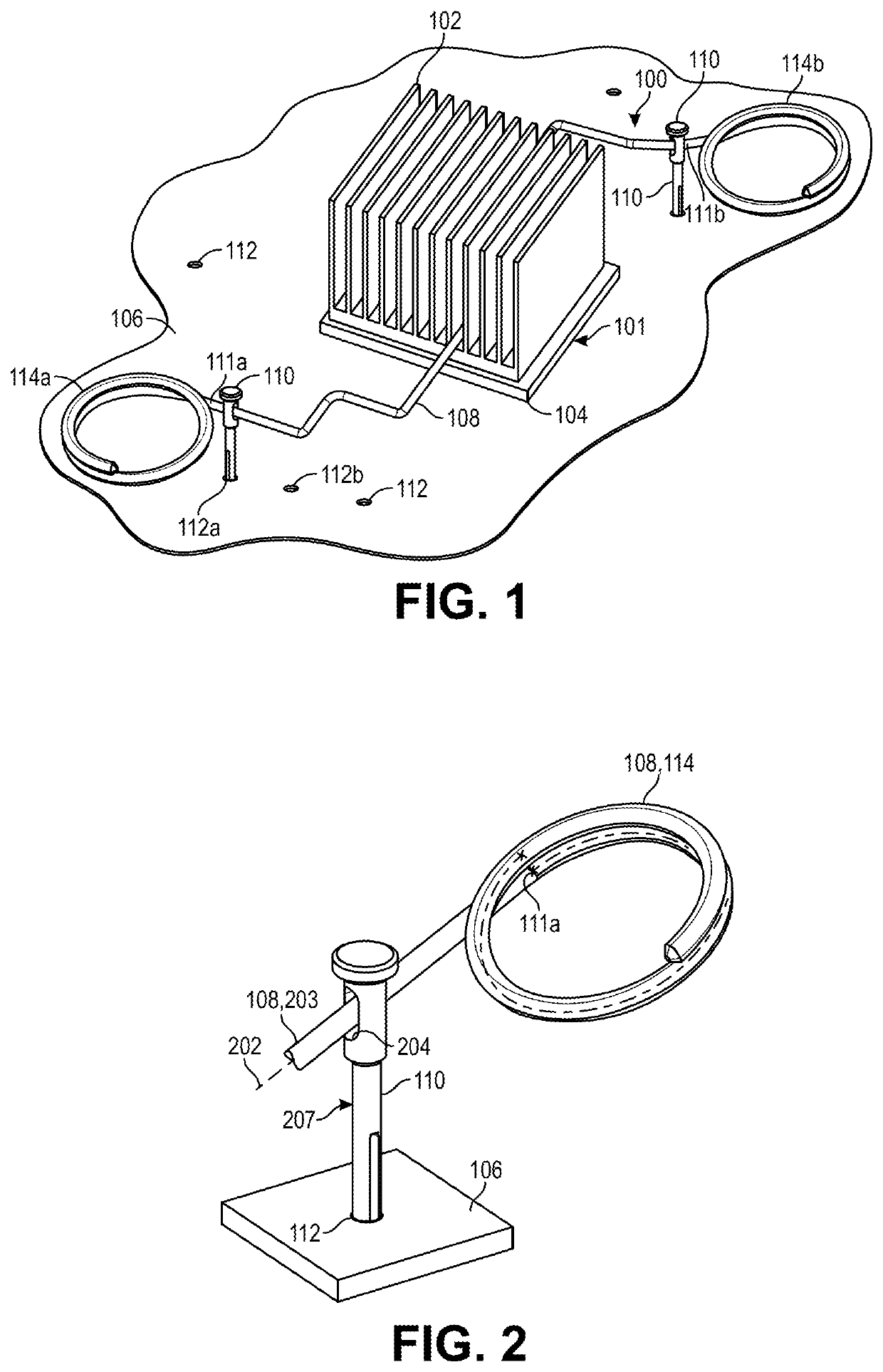
[0031]Embodiments describe a heatsink retainer assembly having one or more heatsink anchors mounted on a retention wire. The heatsink retainer assembly may be used to retain a heatsink against an integrated circuit mounted on a printed circuit board (PCB). The heatsink retainer assembly may also be used in other applications, such as to retain a heatsink against another heat source on or off of a PCB, and thus, reference to the heatsink retainer assembly as being used to retain a heatsink against an integrated circuit on a PCB is not limiting.

[0032]In various embodiments, description is made with reference to the figures. However, certain embodiments may be practiced without one or more of these specific details, or in combination with other known methods and configurations. In the following description, numerous specific details are set forth, such as specific configurations, dimensions, and processes, in order to provide a thorough understanding of the embodiments. In other instan...


PUM


Abstract

A heatsink retainer assembly, and components of the heatsink retainer assembly, are described. The heatsink retainer assembly includes one or more heatsink anchors mounted on a heatsink retention wire between several stops. The anchors include channels to receive the retention wire such that the anchors can slide over the retention wire between the stops. The stops retain the anchors on the retention wire. The anchors can be inserted into respective mounting holes of a carrier substrate by pressing the anchors into the mounting holes on a side of the carrier substrate carrying a heat source. A heatsink can be mounted on the heat source and the retention wire can extend over the heatsink to retain the heatsink against the heat source when the anchors are secured to the carrier substrate. Other embodiments are described and claimed.

Description

[0001]This application claims the benefit of U.S. Provisional Patent Application No. 62 / 826,837, filed on Mar. 29, 2019, which is incorporated herein by reference in its entirety to provide continuity of disclosure.FIELD[0002]The present disclosure relates to retention devices for heatsinks. More specifically, the present disclosure relates to retention devices for retaining heatsinks against electronic components mounted on a printed circuit board.BACKGROUND INFORMATION[0003]Printed circuit boards (PCBs) support and electrically connect electronic components of various types on a top side of the PCB. For example, passive electronic components such as resistors, inductors, or capacitors can be mounted on a PCB. Similarly, active electronic components such as integrated circuits can be mounted on the PCB. The electronic components generate heat during use, and the heat can be conducted and radiated away from the electronic components using a heatsink. For example, the heatsink can be...

Claims


Application Information

Patent Timeline
Patent Type & Authority Applications(United States)
IPC IPC(8): H01L23/40H05K7/20
CPCH01L2924/0002H01L23/4093H05K7/20418H01L23/40
Inventor SIN YAN TOO, THIERRYMASTO, ANDREW RICHARD
Owner RADIAN THERMAL PROD
Learn More