Auto phase control drive circuit for gyroscope apparatus

a technology of gyroscope and drive circuit, which is applied in the direction of speed measurement using gyroscopic effects, instruments, surveying and navigation, etc., can solve the problems of phase difference between the pick-off signal and the drive signal, and electronic parts tend to change their electrical characteristics

Active Publication Date: 2020-10-01
PANASONIC INTELLECTUAL PROPERTY MANAGEMENT CO LTD
View PDF0 Cites 0 Cited by
  • Summary
  • Abstract
  • Description
  • Claims
  • Application Information

AI Technical Summary

Benefits of technology

[0007]The second circuit is configured to be electrically connected with the first circuit and to change a capacitance of the variable capacitor of the first circuit based on the first signal and the second signal to decrease a phase difference between the first signal and the second signal.

Problems solved by technology

However, a phase difference between the pick-off signal and the drive signal occurs due to the resistance, the capacitance, or the inductance of these electrical parts.
Furthermore, these electronic parts tend to change their electrical characteristics, such as capacitance, inductance, and resistance, depending on environment variations such as temperature, humidity, pressure, etc.

Method used


Image

  • Auto phase control drive circuit for gyroscope apparatus
  • Auto phase control drive circuit for gyroscope apparatus

Examples


Embodiment Construction

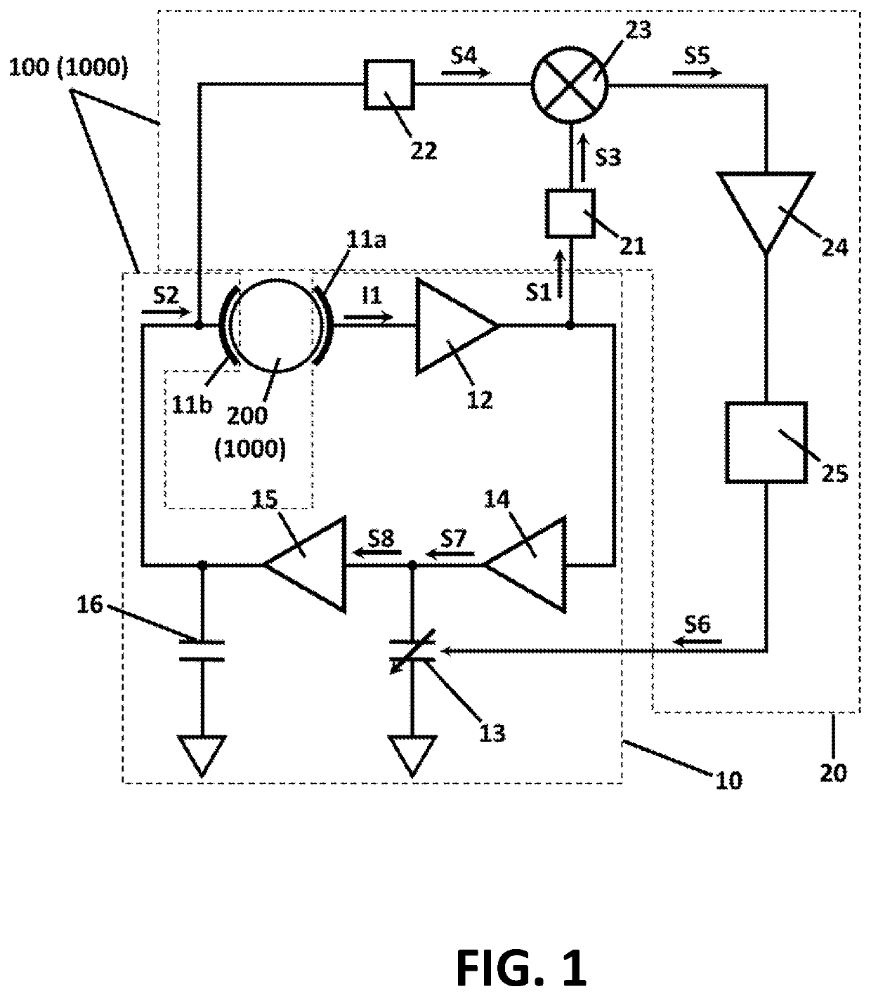
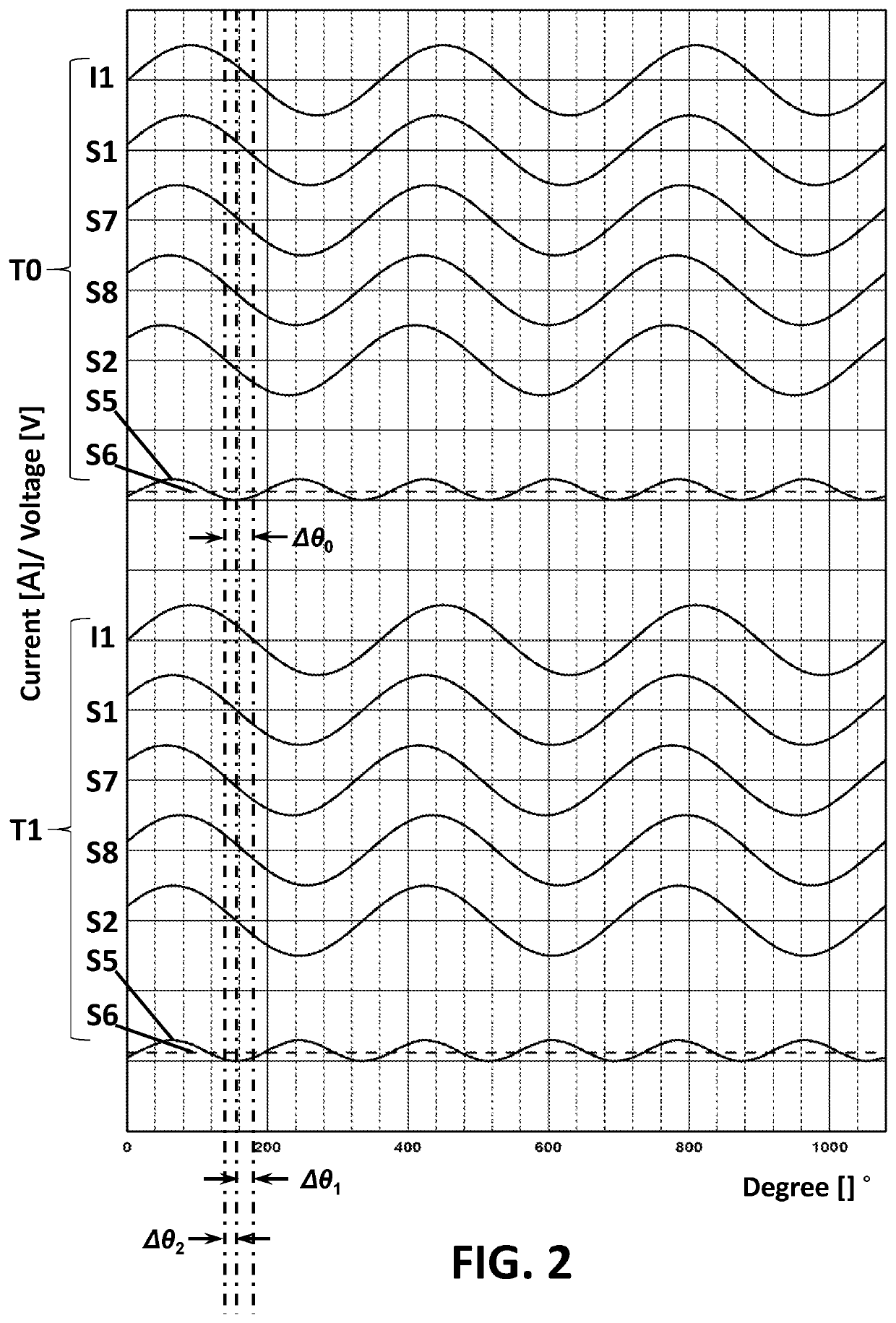
[0012]The following structural or functional descriptions of example embodiments described herein are merely intended for the purpose of describing the example embodiments described herein and may be implemented in various forms. Here, the example embodiments are not construed as limited to the disclosure and should be understood to include all changes, equivalents, and replacements within the technical idea of the present disclosure.

[0013]Hereinafter, example embodiments will be described in detail with reference to the accompanying drawings. Regarding the reference numerals assigned to the elements in the drawings, it should be noted that the same elements will be designated by the same reference numerals, wherever possible, even though they are shown in different drawings. Also, in the description of example embodiments, detailed description of well-known related structures or functions will be omitted when it is deemed that such description will cause ambiguous interpretation of...


PUM


Abstract

An auto phase control drive circuit for a gyroscope apparatus is disclosed. The gyroscope apparatus has a gyro resonator, and the circuit comprises a first circuit and a second circuit. The first circuit includes a first electrode configured to face the gyro resonator, a first amplifier configured to be electrically connected with the first electrode and output a first signal, a variable capacitor electrically connected with the first amplifier, a second electrode configured to face the gyro resonator, to receive a second signal and to be electrically connected with the variable capacitor. The second circuit is configured to be electrically connected with the first circuit and to change a capacitance of the variable capacitor of the first circuit based on the first signal and the second signal to decrease a phase difference between the first signal and the second signal.

Description

BACKGROUNDField of the Invention[0001]At least one example embodiment relates to a drive circuit for a gyroscope apparatus, and more particularly, the drive circuit for a gyroscope apparatus having a phase controller to correct phase errors.Description of the Related Art[0002]Japanese Patent No. 5369525B2 discloses an example of a conventional drive circuit for a gyroscope apparatus. The conventional drive circuit for a gyroscope apparatus has a pair of electrodes and a plurality of electronic parts, such as amplifiers, capacitors, and resistors. These electronic parts are connected between two electrodes. Here, the drive circuit is configured to drive a voltage onto a drive electrode, measure the received signal (response of the gyroscope to this drive voltage) at a pick-off electrode, and provide the necessary amplification and phase adjustment between these two electrodes for a feedback loop to sustain oscillation at a gyroscope resonance frequency.[0003]Ideally, it is preferred ...

Claims


Application Information

Patent Timeline
Patent Type & Authority Applications(United States)
IPC IPC(8): G01C19/5776
CPCG01C19/5776
Inventor LIPKA, RONALD JOSEPHXIAO, HONG
Owner PANASONIC INTELLECTUAL PROPERTY MANAGEMENT CO LTD
Why Eureka
Try Eureka