
Method for manufacturing an endoscope

a manufacturing method and endoscope technology, applied in the direction of manufacturing tools, other manufacturing equipment/tools, manufacturing apparatus, etc., can solve the problems of relative complexity, and achieve the effect of convenient and reliable window insertion

Pending Publication Date: 2020-10-01
OLYMPUS WINTER & IBE
View PDF0 Cites 1 Cited by
  • Summary
  • Abstract
  • Description
  • Claims
  • Application Information

AI Technical Summary

Benefits of technology

The patent is about a way to easily and reliably insert a window into the end of an endoscope. The method involves using a solder preform between the window and the endoscope shaft, which can be heated to create a strong and tight seal between the window and the endoscope. This process is efficient and effective, and can produce an autoclavable and chemically stable endoscope.

Problems solved by technology

This is relatively complex.

Method used


Image

  • Method for manufacturing an endoscope
  • Method for manufacturing an endoscope
  • Method for manufacturing an endoscope

Examples


Embodiment Construction

[0047]FIG. 1 shows a schematic and simplified side view of a surgical instrument 2 such as an endoscope. At its distal end, it comprises a tubular endoscope shaft 4 with a lens system that makes it possible to observe a surgical or investigated region lying distally in front of the free end of the endoscope shaft 4. The endoscope shaft 4 terminates in a housing 6 that has an eyepiece 8 at the proximal end. The housing 6 is for handling the surgical instrument 2. On the side of the housing 6 is a light source 10 such as an LED light source. This is connected by a connecting cable 12 to a suitable power supply.

[0048]A schematically shown camera head 14 with an ocular adapter (not shown) is arranged on the eyepiece 8. The camera head 14 detects the light exiting the ocular of the surgical instrument 2 with its own lens system, and images it on an optical surface sensor such as a CCD or CMOS chip. The camera head 14 is supplied with power by means of a connection 16. Furthermore, it is ...


PUM

PropertyMeasurementUnit
widthaaaaaaaaaa
widthaaaaaaaaaa
widthaaaaaaaaaa

Abstract

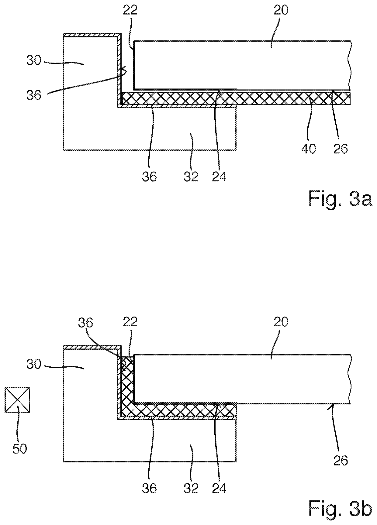
A method for the manufacturing an endoscope, the method including: providing a window having a lateral peripheral surface and a flat surface, the window is provided with a metal coating on a lateral peripheral surface and / or an edge region of the flat surface, and the flat surface of the window is provided with a solder preform, inserting the window provided with the solder preform into a window seat of an endoscope shaft of the endoscope, where the flat surface of the window one of faces an interior space of the endoscope shaft or faces away from the interior space of the endoscope shaft, and subsequent to the inserting, heating the solder preform with a heating device such that solder material of the solder preform is distributed between the window and the window seat and, after the solder material cools, solder is arranged between the window and the window seat.

Description

CROSS-REFERENCE TO RELATED APPLICATION[0001]The present application claims the benefit to DE 10 2019 108 117.3 filed on Mar. 28, 2019, the entire contents of which is incorporated herein by reference.BACKGROUNDField[0002]The present disclosure relates to a method for manufacturing an endoscope as well as the use of a window and a solder preform for manufacturing an endoscope having an endoscope shaft.Prior Art[0003]Video endoscopes normally have a window on their proximal end in order to be able to look at objects to be observed on the distal end or near the distal end of the endoscope. Inside the video endoscope in the area of the window, i.e. on the proximal end, a camera can be provided, for example, which can take pictures through a corresponding window, which is provided on the distal end of the endoscope. Alternatively, optical fibers and, if applicable, optics can be provided in order to direct pictures from the distal end of the endoscope to the proximal end.[0004]With endos...

Claims


Application Information

Patent Timeline
Patent Type & Authority Applications(United States)
IPC IPC(8): A61B1/00B23K1/00B23K1/002
CPCA61B1/0011B23K1/0008B23K1/002A61B1/00096B23K2101/20B23K1/0056
Inventor SCHOELER, UWETORKUHL, NILS
Owner OLYMPUS WINTER & IBE
Learn More