
A cutting element for use in a hair cutting device, and a method of manufacturing the same

a cutting element and cutting device technology, applied in the direction of manufacturing tools, instruments, fibre light guides, etc., can solve the problems of reducing requiring replacement, and reducing the efficiency of shaving devices, so as to reduce the effectiveness of shaving devices and reduce the cost. , the effect of high precision

Inactive Publication Date: 2020-09-24
KONINKLJIJKE PHILIPS NV
View PDF0 Cites 0 Cited by
  • Summary
  • Abstract
  • Description
  • Claims
  • Application Information

AI Technical Summary

Benefits of technology

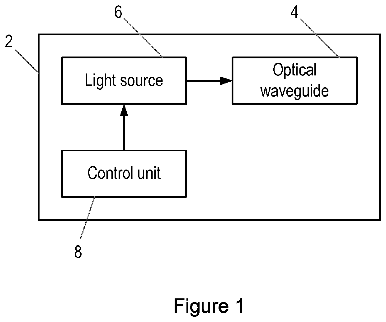
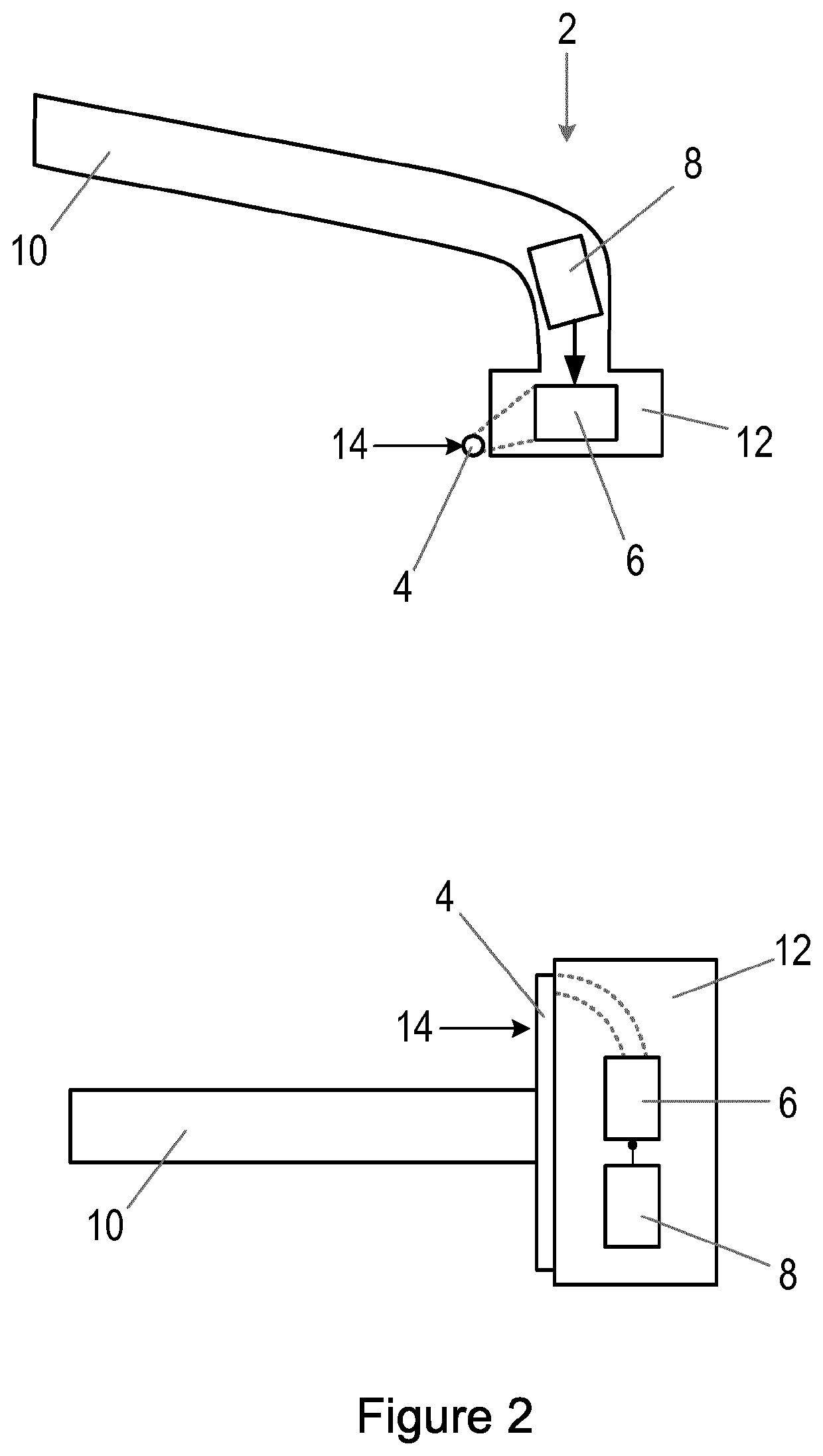
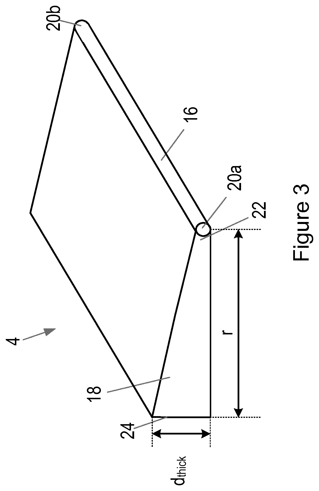
The patent text describes a cutting element for use in a hair cutting device that is made with a special optical waveguide. The waveguide has a core and a support structure that contacts the core to hold it in place. The support structure tapers linearly or non-linearly from a thin side to a thick side to reduce its effectiveness. The cutting element is made by a method that involves forming a shaped preform by removing a portion of the outer layer of the optical waveguide, heating it, and pulling it to reduce its cross-section. The support structure is shaped to attach to the hair cutting device or align it with it. The technical effect of this design is that the cutting element is fragile and easily damaged during use, requiring replacement frequently. The method of manufacturing the cutting element provides a way to improve its durability and performance.

Problems solved by technology

A fiber optic with reduced or removed cladding as described above will be extremely fragile and not able to sustain typical mechanical forces arising due to the contact of the fiber optic on the skin and hair of a subject.
As such, the fiber optic is likely to break or otherwise be damaged during use and require replacement.
The fiber optic in the above-mentioned shaving device can have a D-shape, which means that coupling light into a hair is difficult as the hair needs to be in contact with the small portion of the exposed core, which reduces the effectiveness of the shaving device.
Moreover, it is difficult to process fiber optics to obtain the required D-shape due to the high precision required and the fragility of the fiber optic.

Method used


Image

  • A cutting element for use in a hair cutting device, and a method of manufacturing the same
  • A cutting element for use in a hair cutting device, and a method of manufacturing the same
  • A cutting element for use in a hair cutting device, and a method of manufacturing the same

Examples


first embodiment

[0060]FIG. 5 illustrates two ways in which light from a light source 6 in the hair cutting device 2 can be coupled into core 16 of the cutting element 4. In a first embodiment, shown in FIG. 5(a), light from the light source 6 can be coupled into the first end 20a of the core 16 via an optical fibre 32 (or other type of optical waveguide) and a prism 34 (or other type of light reflecting component). The use of prism 34 provides a compact arrangement for coupling the light into the core 16. A second prism 36 (or other type of light reflecting component) can be provided at the second end 20b of the core 16 for coupling light that has passed through the core 16 into a second optical fibre 38. The second prism 36 and second optical fibre 38 remove light from the cutting element 4 (which is close to the skin of the subject) in order to avoid the cutting element 4 being heated by the light. It will be appreciated that alternative structures can be used for this purpose, and the structure ...

second embodiment

[0062]In the second embodiment shown in FIG. 5(b), a first light guide 40 can be provided between the first optical fibre 32 and the prism 34 to improve the coupling of light from the light source 6 to the core 16. Likewise, a second light guide 42 can be provided between the prism 36 and the second optical fibre 38 to improve the coupling of light from the core 16 to the second optical fibre 38. The first light guide 40 can be provided with a lens or other optical element at the coupling with the first optical fibre 32 for focusing the light from the light source 6 into the first light guide 40.

[0063]FIG. 6 illustrates a preferred arrangement of the coupling between the light source 6 and the core 16. In particular, to reduce or avoid power loss, the diameter Φin of the first optical fibre 32 (in the FIG. 5(a) embodiment) or the first light guide 40 (in the FIG. 5(b) embodiment) is less than the diameter d of the core 16. To reduce or avoid power loss in the coupling from the core ...


PUM

PropertyMeasurementUnit
wavelengthsaaaaaaaaaa
diameteraaaaaaaaaa

Abstract

There is provided a method of manufacturing a cutting element for use in a hair cutting device, the cutting element comprising an optical waveguide, the method comprising providing a preform for an optical waveguide, the preform comprising a core and an outer layer, wherein the outer layer is arranged around the core along the length of the core; forming a shaped preform by removing a portion of the outer layer along the length of the core to expose part of the core, wherein a remaining portion of the outer layer is a support structure for the core; heating the shaped preform; and pulling the shaped preform in the direction of the axis of the core to reduce the cross-section of the shaped preform and form the optical waveguide. Also provided is a cutting element manufactured according to the above method and a cutting element for use in a hair cutting device, the cutting element comprising an optical waveguide comprising a core and a support structure, wherein the support structure contacts the core along the length of the core to support the core, and wherein part of the core is exposed along the length of the core to form a cutting face for contacting hair. The thickness of the support structure tapers linearly or non-linearly from a thin side at which the support structure contacts the core to a thick side.

Description

FIELD OF THE INVENTION[0001]The invention relates to a cutting element for use in a hair cutting device, and a method of manufacturing the same, and in particular to a cutting element that comprises an optical waveguide.BACKGROUND OF THE INVENTION[0002]Shaving devices for cutting or shaving hair on a body of a subject typically make use of one or more blades that cut hairs as the blade is moved across the skin of the subject. The blades can be static within the device, for example as in a wet razor, whereas in other types of devices, for example electric shavers, one or more blade elements can be actuated (e.g. rotated or oscillated) in order to produce a cutting action.[0003]However, an alternative type of shaving device has been proposed in WO 2014 / 143670 that makes use of laser light. In particular a laser light source is provided that is configured to generate laser light having a wavelength selected to target a predetermined chromophore to effectively cut a hair shaft. A fiber ...

Claims


Application Information

Patent Timeline
Patent Type & Authority Applications(United States)
IPC IPC(8): F21V8/00C03B37/012A45D26/00G02B6/02G02B6/25B26B21/40B26B21/48G02B6/28
CPCG02B6/2826C03B2203/02C03B37/01234G02B6/02B26B21/48A45D26/0009B26B21/4081G02B6/001G02B6/25A61B18/203A61B2018/00476C03B37/01228
Inventor BOURQUIN, YANNYK PARULIAN JULIANTER BORCH, JOSEPH PETRUS HENRICUSJUTTE, PETRUS THEODORUSTHUMMA, KIRAN KUMARMOESKOPS, BASTIAAN WILHELMUS MARIAVERHAGEN, RIEKOJOHNSON, MARK THOMAS
Owner KONINKLJIJKE PHILIPS NV
Learn More