
Trimable tail kit rudder

a technology of tail kit and guided munition, which is applied in the direction of weapons, projectiles, weapons types, etc., can solve the problems of generating a significant amount of drag, difficult processing, and difficult control of the trajectory of the munition, so as to reduce the overall drag of the projectile, reduce the strake dynamic pressure, and reduce the effect of bearing friction

Active Publication Date: 2020-09-24
BAE SYST INFORMATION & ELECTRONICS SYST INTERGRATION INC
View PDF0 Cites 6 Cited by
  • Summary
  • Abstract
  • Description
  • Claims
  • Application Information

AI Technical Summary

Benefits of technology

The present patent text describes a system with a tail kit assembly that has multiple, trimmable control surfaces, rudders, flaps or tabs to reduce the drag on a projectile. These trimmable control surfaces, rudders, flaps or tabs can be modulated up to 50 to 200 Hz, which reduces the overall drag on the projectile. The trimmable control surfaces, rudders, flaps or tabs feature a design that allows the tail kit base to continue to rotate in the original rotational direction of the projectile body. The independent modulation of the control surfaces reduces drag and allows for increased range and overall mission effectiveness.

Problems solved by technology

When a guidance system is utilized in a gun-fired munition, controlling the trajectory of the munition is often problematic because the tail kit assembly needs to de-roll using strakes and place the rudder in the direction of the course correction.
Gun-fired munitions can spin at a rotational rate of about 20,000 rpm causing the attached tail kit assembly to rotate, thus making calculation of its rotational orientation, which is essential for effectively guiding the munition, quite difficult and processor intensive.
This results in aggressive strakes having a large surface area which interacts with the airstream to generate the needed control dynamics, thereby generating a significant amount of drag.
Such drag forces have a substantial negative effect on the velocity of the round and leads to a significant reduction in the effective range of such a guided munition.
While known tail kit assemblies facilitate guidance of such a round, the approximately 30% drop in the effective range of the round is undesirable.

Method used


Image

  • Trimable tail kit rudder
  • Trimable tail kit rudder
  • Trimable tail kit rudder

Examples


Embodiment Construction

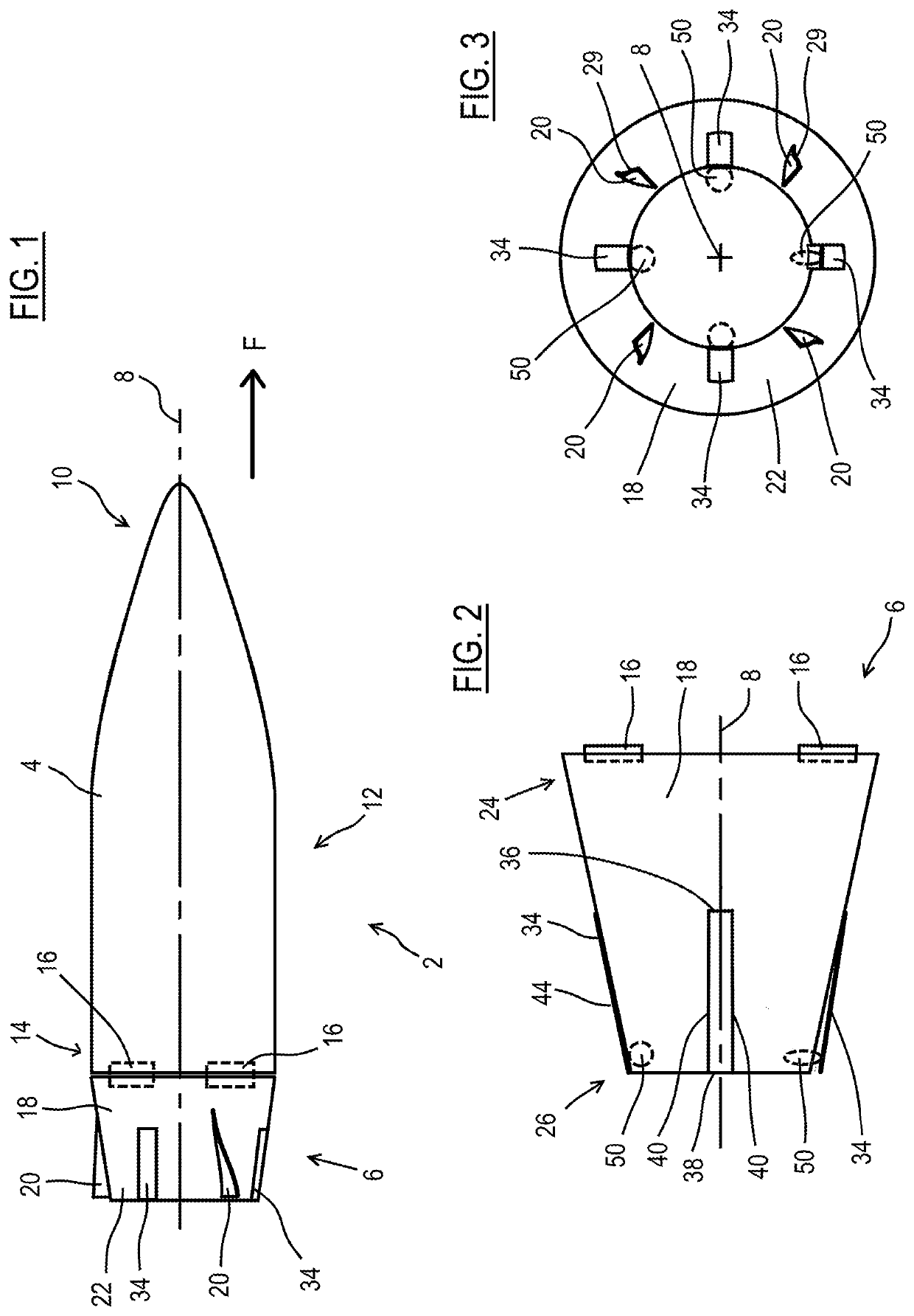
[0021]FIG. 1 illustrates one embodiment of a gun fired munition according to the present disclosure. As used herein a munition should be understood as being a projectile, bullet, load, round or asset that is fired, shot, or launched from ordnance having a fire control system. The munition described in more detail below may have a small or medium caliber, ranging from 25 mm to 57 mm, or more specifically the munition has a caliber of 30 mm. When fired, the munition passes through a rifled barrel which causes the munition to rotate as it is discharged from the muzzle. Due to the rifling of the barrel small munitions of the type described herein have a rotational rate of 20,000 RPM.

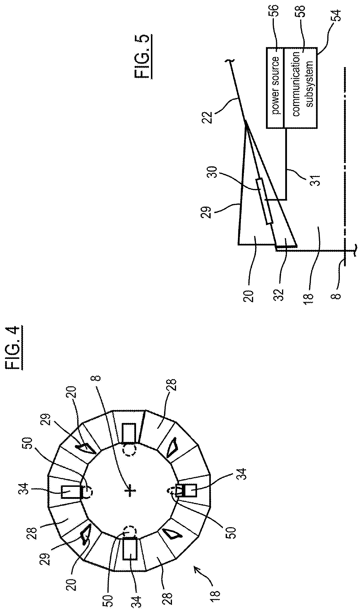
[0022]Still referring to FIG. 1, the munition 2 has, with respect to a direction of flight F, a leading front body 4 and a trailing tail kit assembly 6 that together define a longitudinal axis 8. The front body 4 has a head end or ogive 10 and a central section 12 that is generally cylindrical in shape. Atta...


PUM


Abstract

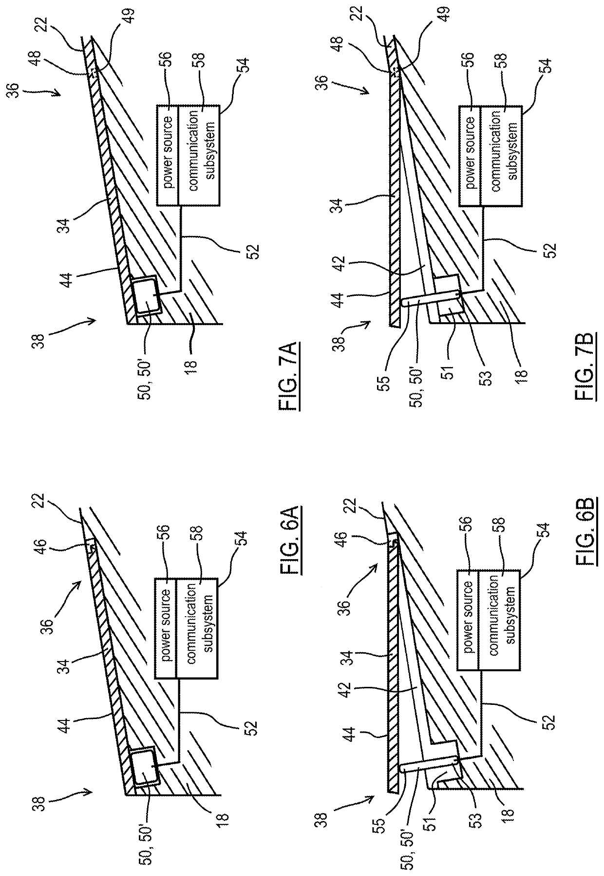
A tail kit assembly of a guided munition having a tail kit base connected to a trailing end of a projectile body. The tail kit base is rotatable relative to the projectile body. A trimmable rudder has forward and rearward ends. The forward end is pivotally coupled to the tail kit base, such that the trimmable rudder can, relative to the tail kit base, between retracted and extended orientations. An actuator is fixed between the tail kit base and the rearward end of the trimmable rudder. The actuator is electrically coupled to an onboard guidance system that controls actuation of the actuator to pivot the trimmable rudder between the retracted orientation and the extended orientation.

Description

FIELD OF THE DISCLOSURE[0001]The present disclosure relates to a tail kit assembly for a guided munition and more particularly to a tail kit assembly for a guided munition having a system of low profile trimmable rudders for guiding the munition along a trajectory.BACKGROUND OF THE DISCLOSURE[0002]Many guided munitions are known to include systems and / or assemblies that function to guide and control the munition by making corrections to its trajectory. These guidance systems typically include subsystems that can communicate with a fire control system which can implement course corrections—up or down and left and right maneuvers to alter or rather correct the course of the munition while in flight. Based on determinations made by guidance algorithms at the fire control system and communicated to the munition, different mechanical components of the munition can be activated or adjusted so as to control the flight path of the munition. These components are often generically referred to...

Claims


Application Information

Patent Timeline
Patent Type & Authority Applications(United States)
IPC IPC(8): F42B10/20F42B10/26
CPCF42B10/20F42B10/26F42B10/64F42B10/60F42B10/62
Inventor CHOINIERE, MICHAEL J.STOCKWELL, JASON T.
Owner BAE SYST INFORMATION & ELECTRONICS SYST INTERGRATION INC
Learn More