Lighting unit for a light device of a motor vehicle and a light device with the lighting unit

a technology of motor vehicles and light devices, which is applied in the direction of lighting and heating equipment, instruments, mechanical equipment, etc., can solve the problems of planar surfaces, motor vehicle lamps must be adapted, and the spread of this technology

Inactive Publication Date: 2020-09-24
VARROC LIGHTING SYST SRO
View PDF0 Cites 2 Cited by
  • Summary
  • Abstract
  • Description
  • Claims
  • Application Information

AI Technical Summary

Benefits of technology

The invention is a lighting unit for a motor vehicle that uses a light guide to direct light rays from a light source. The light guide has front and rear surfaces, with exit areas for the output of light rays and intermediate areas for total reflection. The lighting unit also includes a light assembly with optical elements that bind and emit light rays. The rear surface of the light guide may have unbinding elements to direct light rays towards the exit areas. The optical elements may be embedded in a carrier or separate from it. The lighting unit can be used in a light device of a motor vehicle and may include filters to influence the color background and the flow direction of light rays. The thickness of the lighting unit is preferably from 0.1 mm to 14 mm. The invention also relates to a light device comprising the lighting unit.

Problems solved by technology

Unfortunately, there are still some limitations of the OLED technology preventing widespread deployment of this technology in the serial production of car lighting.
E.g. service life, penetration of moisture, low luminance for power functions, limitation to planar surfaces only and last, but not least, a high price.
Another drawback of the OLED technology is the fact that a lamp of a motor vehicle must be adapted do detect an error status of the light source.
The situation of planar sources is more complicated because OLED's comprise organic layers that emit light after connection of electric voltage / current.
The disadvantage of the above-mentioned design solutions is that these lighting units are not intended to be used as external lighting equipment for motor vehicles, for which a variety of technical specifications and regulatory requirements must be followed and fulfilled.
For example, chemically cured cover glass that is used in the manufacturing process of screens is unsuitable for use as a cover glass of motor vehicle headlights as its manufacturing costs are too high.
However, there are cases when the requirements of all regulations cannot be met with the use of a single design of a lighting function.
Thus, it is not desirable to strive to achieve this (Lambertian) distribution, which is close to the distribution that OLED lights or some displays work with.
As indicated above, fading at large viewing angles is rather considered as a defect in the case of displays and TV screens.
This is because in most cases, the use of a simple square or rectangular surface is not acceptable from a designer point of view.
Today, the style of a car is a very important parameter and at the same time a limit for meeting technical and legislative requirements.
A disadvantage of these designs is the fact that the light rays are diffused with a relatively large lateral dispersion.
Another drawback of the above-mentioned designs is the entire structural arrangement of the optical parts, which does not enable their variable configuration based on designer requirements, e.g. if it is necessary to direct the light beam in a certain manner, or if a spatial shape of an optical element is to be achieved.

Method used


Image

  • Lighting unit for a light device of a motor vehicle and a light device with the lighting unit
  • Lighting unit for a light device of a motor vehicle and a light device with the lighting unit
  • Lighting unit for a light device of a motor vehicle and a light device with the lighting unit

Examples


Embodiment Construction

OF EMBODIMENTS OF THE INVENTION

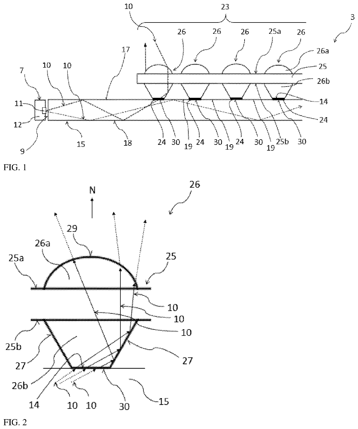
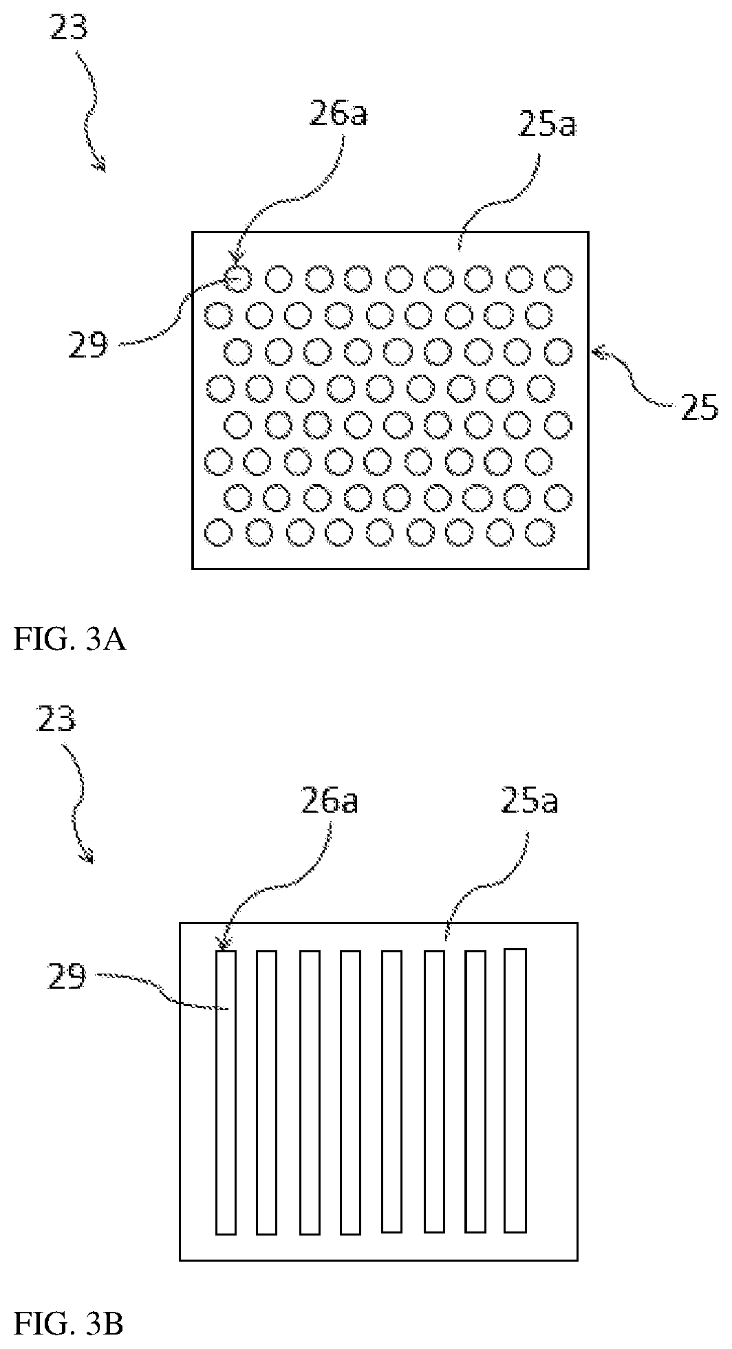
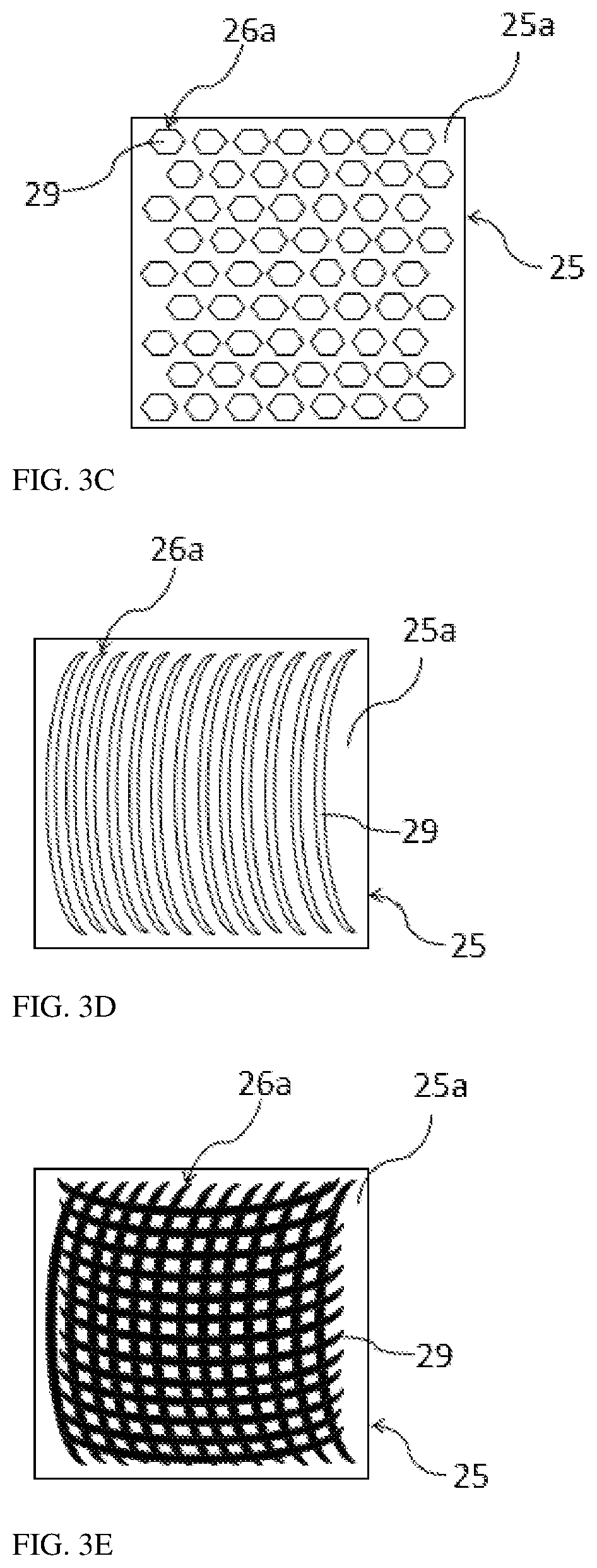
[0053]FIGS. 1 to 15b show embodiment examples of the lighting unit 3 according to the invention.

[0054]The lighting unit 3 comprises a light guide 15 made of an optically transparent material, with an associated light unit 7 comprising light sources 11 situated on a carrier 12. The light guide 15 can e.g. be of a plate-like shape (a panel-shaped light guide) and have a constant or variable thickness, or be of an elongated shape (rod light guide), it may be straight, bent, undulated or spatially shaped. The light sources 11 are situated at the entry area 9 of the light guide 15 and are designed to emit light rays 10 into the light guide 15. These light rays 10 pass along the light guide 15 using the total reflection principle, which occurs on the rear surface 18 and front surface 17 of the light guide 15 which form interfaces between the light guide 15 and the surroundings of the light guide 15 with a low refractive index with respect to the refractive i...


PUM


Abstract

The lighting unit (3) comprises a light guide (15) to lead light rays (10) from at least one light source (11) wherein the light guide (15) comprises the front surface (17) and the opposite rear surface (18). The front surface (17) comprises exit areas (30) for the exit of light rays (10) from the light guide (15), and intermediate areas (19) positioned between the exit areas (30) and configured for total reflection of light rays (10) passing along the light guide (15). The lighting unit (3) further comprising a light assembly (23) situated against the front surface (17) of the light guide (15) and comprising optical elements (26) containing a bearing area (14) with which the optical elements (26) are connected to the opposite exit areas (30) directly or indirectly in such a way that transitional layers (24) are situated between the exit areas (30) and bearing areas (14). The optical elements (26) are configured to bind light rays (10) falling onto the exit areas (30) and to emit them from the exit surface (29) of the optical elements (26) averted from the light guide (15), in a predetermined direction or directions.

Description

RELATED APPLICATIONS[0001]This application claims the priority benefit of Czech Patent Application Serial No. PV 2019-176 entitled “A lighting unit for a light device of a motor vehicle and a light device with the lighting unit,” filed Mar. 22, 2019, the entire disclosure of which is incorporated herein by reference.FIELD OF THE INVENTION[0002]The invention relates to a lighting unit for a light device of a motor vehicle and a light device with the lighting unit.BACKGROUND INFORMATION[0003]New vehicle lighting systems do not only focus on the optical output increasing the driving comfort and traffic safety, but it is also the appearance that is important for modern light devices of motor vehicles as headlights or signal lamps of a motor vehicle. Modern point and planar light sources, especially LED and OLED sources, have opened a new chapter for new stylistic options of car designers.[0004]Using a planar light source, especially OLED—Organic Light Emitting Diodes—brings not only an ...

Claims


Application Information

Patent Timeline
IPC IPC(8): F21S41/24F21V8/00F21S41/25G02B7/02
CPCF21S41/25G02B7/027G02B6/0023F21S41/24B60Q1/04B60Q1/26F21S41/141G02B6/24F21S43/14F21S43/239F21S43/245F21S43/255F21S43/26F21S43/315F21S43/40G02B6/0045G02B6/0053G02B6/0055
Inventor GLOSS, TOMASSIMURDA, VITHRUSKA, JAKUB
Owner VARROC LIGHTING SYST SRO
Why Eureka
Try Eureka