Eureka AIR delivers breakthrough ideas for toughest innovation challenges, trusted by R&D personnel around the world.

Configuration of landing gear assemblies for an aircraft

a technology for landing gear and aircraft, which is applied in the direction of aircraft, vehicles, wheel arrangements, etc., can solve the problems of occupying more space, requiring significant structural redesign of the fuselage and associated principal load bearing structure of the aircraft, and increasing the weight of the aircra

Active Publication Date: 2020-09-24
AIRBUS OPERATIONS LTD
View PDF0 Cites 4 Cited by
  • Summary
  • Abstract
  • Description
  • Claims
  • Application Information

AI Technical Summary

Benefits of technology

This patent describes an aircraft design with two main landing gear assemblies. One assembly is placed on each side of the aircraft. These assemblies use a single axle with wheels and brakes to slow down the aircraft in a way that aligns with the direction of travel. The landing gear legs are designed to allow for efficient stowage in the limited space allowed for by the aircraft. The design also includes a low-friction landing gear option that uses an air cushion and a pitch trimmer to further improve stowage. Additionally, there is a main load bearing strut that is visible from the ground and has a frangible portion to prevent damage to the aircraft in the event of failure. This design approach allows for efficient use of space and provides safety measures to prevent accidents.

Problems solved by technology

The provision of four-wheeled MLGs, each with an associated landing gear bogie, takes up more space when stowed and adds significantly more weight to the aircraft.
Such a proposal would however require significant structural redesign of the fuselage and associated principal load bearing structures of the aircraft.

Method used


Image

  • Configuration of landing gear assemblies for an aircraft
  • Configuration of landing gear assemblies for an aircraft
  • Configuration of landing gear assemblies for an aircraft

Examples


Embodiment Construction

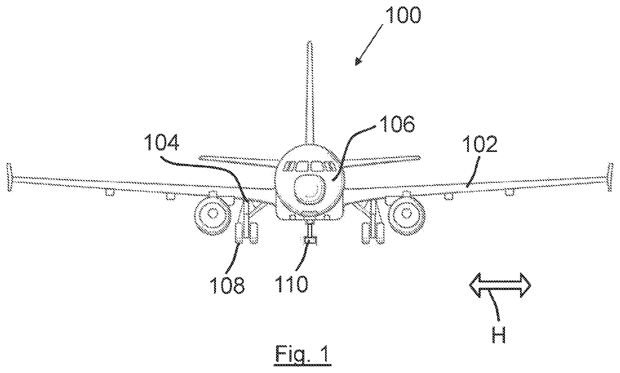
[0042]FIG. 1 shows an aircraft in accordance with a first embodiment of the invention. The aircraft 100 comprises two wings 102 and four retractable landing gear assemblies (three of which being shown in FIG. 1). There are two main landing gear assemblies 104, each being mounted on a respective wing of the aircraft. The two main landing gear assemblies each fold inboard to be stowed partially within the fuselage 106. A nose landing gear is also provided (removed from view in FIG. 1). The two main landing gear assemblies 104 and the nose landing gear each carry two wheels 108 arranged coaxially on a single axle (in diablo formation) for rolling on the ground when the aircraft is on the ground. The aircraft 100 has a maximum take-off weight (MTOW) of about 120 tonnes, and an operating empty weight of about 65 tonnes. The weight of the aircraft is therefore just over the weight at which it would be appropriate for only six wheels to carry the entire weight of the aircraft. In accordanc...


PUM


Abstract

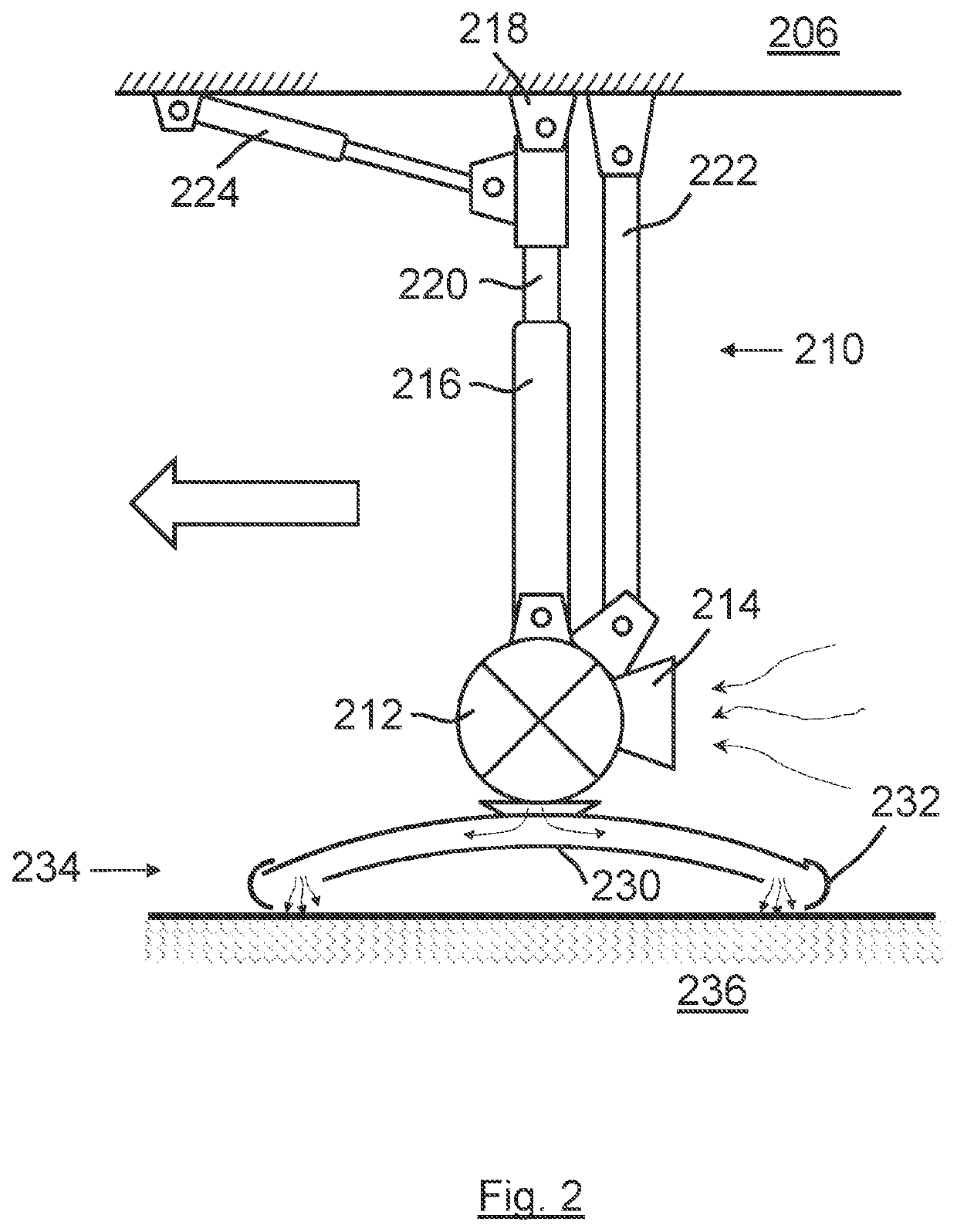
An aircraft having a retractable landing gear assembly configured to support some of the weight of the aircraft via one or more wheels, and another retractable non-wheeled landing gear assembly or device configured to support some of the weight of the aircraft via one or more “low-friction” supports such as an air cushion is disclosed. The aircraft may have a maximum take-off weight between 100 and 150 tonnes. There may be two main landing gears each carrying two wheels, a nose landing gear, and a central non-wheeled landing gear providing the low friction vertical support when the aircraft is moving on the ground / operating surface.

Description

CROSS RELATED APPLICATION[0001]This application claims priority to United Kingdom (GB) Patent Application 1902748.1, filed Feb. 28, 2019, the entire contents of which is hereby incorporated by reference.BACKGROUND OF THE INVENTION[0002]The present disclosure relates to landing gear assemblies for an aircraft and their configuration. More particularly, but not exclusively, this invention concerns an alternative arrangement of landing gear assemblies on a fixed wing commercial passenger aircraft having a maximum take-off weight of at least 50 tonnes. The invention also concerns a method of operating an aircraft.[0003]An aircraft, for example a fixed wing commercial aircraft of the type arranged to carry at least 50 passengers, requires support on the ground, which may for example be provided by wheeled landing gear assemblies. Airport operators typically place limits on the amount of load that can be supported by a single wheel of the aircraft. Thus heavier aircraft tend to have more ...

Claims


Application Information

Patent Timeline
IPC IPC(8): B60V3/08B64C25/10
CPCB60V3/08B64C25/34B64C25/10B64C25/14B64C25/12B64C25/66
Inventor WILSON, FRASER
Owner AIRBUS OPERATIONS LTD
Why Eureka
Eureka Blog
Learn More