
System and method for controlling charge and discharge of battery

a battery and charging system technology, applied in the direction of battery/fuel cell control arrangement, secondary cell servicing/maintenance, instruments, etc., can solve the problems of low battery may not be efficiently controlled as desired at a low/high temperature, etc., to improve the charge and discharge efficiency of auxiliary batteries

Active Publication Date: 2020-09-10
HYUNDAI MOTOR CO LTD +1
View PDF0 Cites 0 Cited by
  • Summary
  • Abstract
  • Description
  • Claims
  • Application Information

AI Technical Summary

Benefits of technology

This patent is about a system and method for controlling the charging and discharging of an auxiliary battery in a vehicle. The system is designed to maximize the heat generation of the battery at a low temperature and to suppress heat generation at a high temperature. By controlling the DC converter, the system ensures that the current of the battery repeatedly becomes a maximum charging current and a maximum discharging current at a low temperature, thus improving the efficiency of the battery. This system also allows the battery to escape from a temperature range where its efficiency is lowered, thus increasing its durability and fuel efficiency of the vehicle.

Problems solved by technology

On the other hand, the auxiliary battery has very low charge and discharge efficiency at a low temperature below a predetermined temperature or at a high temperature above a predetermined temperature due to chemical properties.
Therefore, even if the control technique included in the cited document is applied, the battery may not be efficiently controlled as desired at a low / high temperature.

Method used

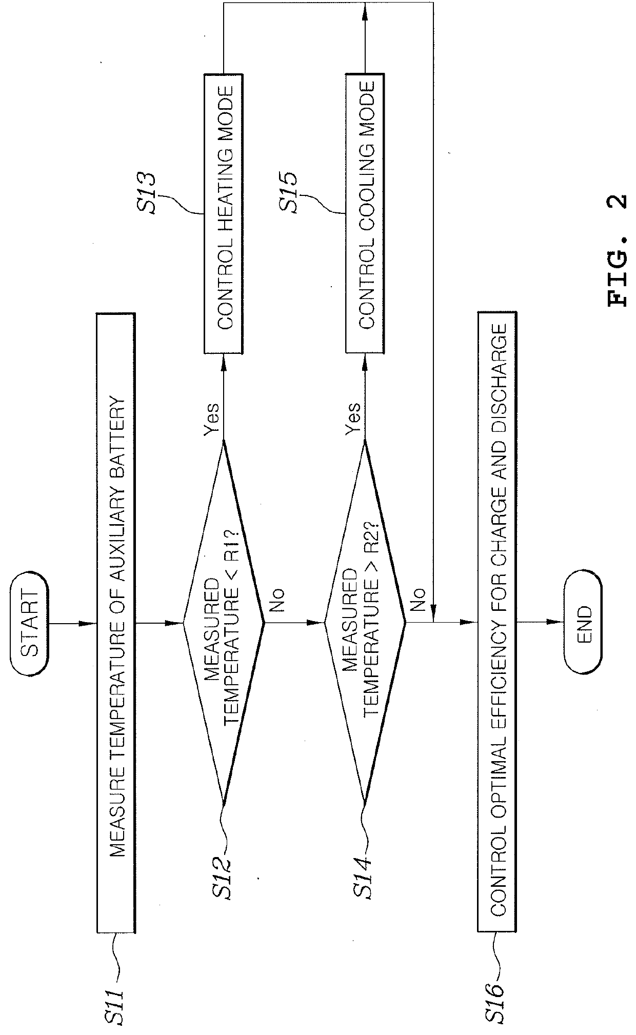
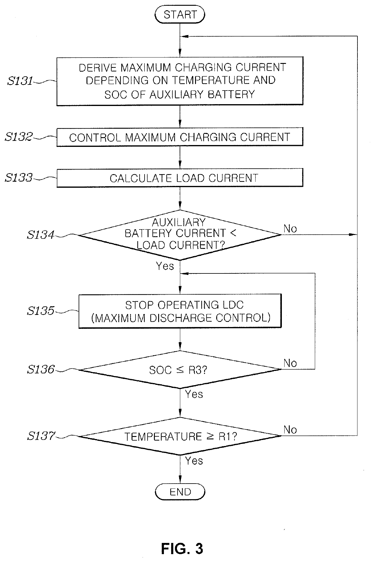

Image

  • System and method for controlling charge and discharge of battery
  • System and method for controlling charge and discharge of battery
  • System and method for controlling charge and discharge of battery

Examples


Embodiment Construction

[0033]Reference will now be made in detail to various embodiments of the present invention(s), examples of which are illustrated in the accompanying drawings and described below. While the present invention(s) will be described in conjunction with exemplary embodiments of the present invention, it will be understood that the present description is not intended to limit the present invention(s) to those exemplary embodiments. On the other hand, the present invention(s) is / are intended to cover not only the exemplary embodiments of the present invention, but also various alternatives, modifications, equivalents and other embodiments, which may be included within the spirit and scope of the present invention as defined by the appended claims.

[0034]Hereinbelow, exemplary embodiments of the present invention will be described in detail with reference to the accompanying drawings.

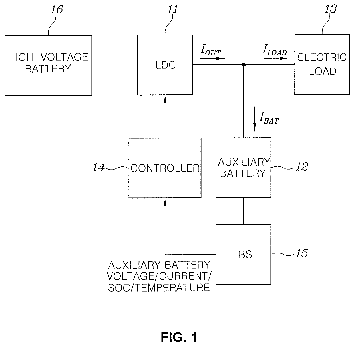
[0035]FIG. 1 is a block diagram illustrating a system for controlling the charge and discharge of a battery ac...


PUM

PropertyMeasurementUnit
input voltageaaaaaaaaaa
temperatureaaaaaaaaaa
electric poweraaaaaaaaaa

Abstract

A method for controlling charge or discharge of a battery in a battery system including a DC converter down-converting an input voltage thereof and outputting an output, a battery connected to an output terminal of the DC converter, and an electric load connected to the output terminal of the DC converter and supplied with electric power from at least one of the DC converter and the battery, may include measuring a temperature of the battery, first controlling, by a controller, an output of the DC converter so that a charging current supplied to the battery from the DC converter becomes a preset maximum value, when the temperature of the battery is lower than a first predetermined temperature, and second controlling, by the controller, the output of the DC converter such that a current of the battery is substantially equal to zero, when the temperature of the battery is higher than a second predetermined temperature which is higher than the first predetermined temperature.

Description

CROSS REFERENCE TO RELATED APPLICATION[0001]The present application claims priority to Korean Patent Application No. 10-2019-0024935 filed on Mar. 4, 2019, the entire contents of which is incorporated herein for all purposes by this reference.BACKGROUND OF THE DISCLOSUREField of the Disclosure[0002]The present invention relates to a system for charging and discharging a battery, and to a system and method for charging and discharging a battery, which allows a battery to rapidly escape from a low- or high-temperature state, thus improving charge and discharge efficiency.Description of Related Art[0003]An eco-friendly vehicle that generates the driving force of a vehicle using an electric motor includes a high-voltage battery that stores high-voltage electrical energy to drive the electric motor, a low-voltage auxiliary battery that supplies electric power to an electric load of the vehicle, and a low-voltage DC converter (LDC) that down-converts the voltage of the high-voltage batter...

Claims


Application Information

Patent Timeline
Patent Type & Authority Applications(United States)
IPC IPC(8): H02J7/00H01M10/44H01M10/615H01M10/63
CPCH01M10/615H01M10/63H02J7/007H01M10/44H01M10/443H01M10/486H01M2010/4278H01M10/425H02J2310/48H02J7/007194H02J7/0068H02J7/00712Y02E60/10B60L2240/545B60L2210/12B60L58/26B60L58/27B60L2240/549B60L2240/529B60L53/22B60L58/13Y02T10/70Y02T10/72Y02T10/7072Y02T90/14B60L58/12B60L53/24G01R31/382B60Y2200/91
Inventor LEE, HO JOONGKIM, HYE SEUNGJEON, JOON YOUNGYOUN, HAN SHINSUNG, WON YONGLEE, DONG JUNJANG, YOUNG JIN
Owner HYUNDAI MOTOR CO LTD
Learn More