Pneumatic Tire

a pneumatic tire and tire technology, applied in the field of pneumatic tires, can solve the problems of degrading drainage performance, degrading rigidity, and affecting the stability of steering on dry road surfaces, so as to improve steering stability performance on wet road surfaces, suppressing pattern noise, and improving steering stability performan

Active Publication Date: 2020-09-10
THE YOKOHAMA RUBBER CO LTD
View PDF0 Cites 2 Cited by
  • Summary
  • Abstract
  • Description
  • Claims
  • Application Information

AI Technical Summary

Benefits of technology

[0007]The present technology provides a pneumatic tire capable of improving steering stability performance on dry road surfaces and steering stability performance on wet road surfaces compared to the related art and suppressing pattern noise.
[0028]According to the pneumatic tire described above, steering stability performance on dry road surfaces and steering stability performance on wet road surfaces can be improved compared to the related art, and pattern noise can be suppressed.

Problems solved by technology

However, when the number of the lug grooves in the tread portion is increased, the rigidity of the tread portion (tread rigidity) is degraded, which degrades steering stability performance on dry road surfaces.
In contrast, when the number of lug grooves in the tread portion is reduced, drainage performance is degraded, which degrades steering stability on wet road surfaces.
Thus, steering stability on dry road surfaces and steering stability on wet road surfaces are inconsistent with each other.
Further, pattern noise is increased by providing the lug grooves.
However, pattern noise caused due to the lug grooves provided in the land portions is not reduced and remains loud.
When the lug grooves are not provided in the land portions, steering stability performance on wet road surfaces is liable to be degraded.

Method used


Image

  • Pneumatic Tire
  • Pneumatic Tire
  • Pneumatic Tire

Examples


Embodiment Construction

[0035]Hereinafter, a pneumatic tire of the present embodiment will be described in detail.

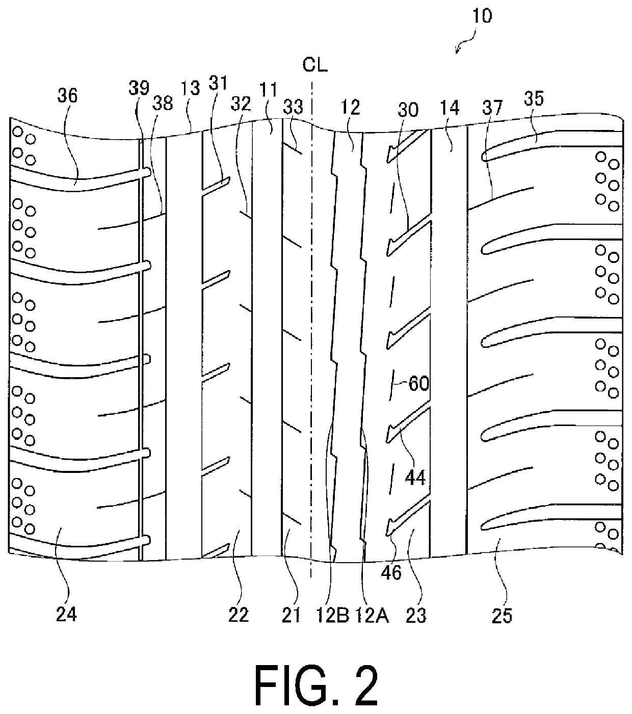
[0036]In the present specification, “tire lateral direction” refers to the direction of the center axis of rotation of a pneumatic tire. “Tire circumferential direction” refers to a rotation direction in which a tread surface rotates, when the tire rotates about the center axis of rotation of the tire. “Tire radial direction” refers to the direction radiating from the center axis of rotation of the tire. “Outward in the tire radial direction” refers to the direction away from the center axis of rotation of the tire. “Inward in the tire radial direction” refers to the direction towards the center axis of rotation of the tire. “Outward in the tire lateral direction” refers to the direction away from the tire equator line in the tire lateral direction. “Inward in the tire lateral direction” refers to the direction toward the tire equator line in the tire lateral direction.

[0037]FIG. 1 is a profile...


PUM


Abstract

A tread pattern of a pneumatic tire includes one center continuous land portion and two intermediate continuous land portions that are divided by four circumferential main grooves and that are not provided with lug grooves. Edges on both sides of one center main groove include groove chamfered portions having a chamfered width changing in the circumferential direction in a zigzag shape. In the regions of the intermediate continuous land portions, first sipes extending inward in the lateral direction from shoulder main grooves of the main grooves, which are positioned on outer sides in the lateral direction, are provided. The first sipes each include a sipe main body portion having a constant distance between sipe wall surfaces on a sipe bottom side and a sipe chamfered portion inclined so that the sipe wall surfaces are open toward the tread surface.

Description

TECHNICAL FIELD[0001]The present technology relates to a pneumatic tire.BACKGROUND ART[0002]For a pneumatic tire, on a tread portion, a tread pattern is formed in which a plurality of main grooves extending in a tire circumferential direction are provided and a plurality of rows of land portions are defined by the plurality of main grooves. In such a pneumatic tire, good drainage performance is achieved by providing a plurality of lug grooves extending in a tire lateral direction in each of the land portions of the tread portion.[0003]However, when the number of the lug grooves in the tread portion is increased, the rigidity of the tread portion (tread rigidity) is degraded, which degrades steering stability performance on dry road surfaces. In contrast, when the number of lug grooves in the tread portion is reduced, drainage performance is degraded, which degrades steering stability on wet road surfaces. Thus, steering stability on dry road surfaces and steering stability on wet ro...

Claims


Application Information

Patent Timeline
Patent Type & Authority Applications(United States)
IPC IPC(8): B60C11/13B60C11/03
CPCB60C11/0302B60C2011/0348B60C2011/0353B60C11/0304B60C2011/0346B60C11/1307B60C11/04B60C11/1323B60C11/1392B60C2011/1209B60C2011/0388B60C2011/0393B60C2011/0381B60C2011/1254B60C11/0306
Inventor TOMOMATSU, RYOUICHI
Owner THE YOKOHAMA RUBBER CO LTD
Why Eureka
Try Eureka