
Leg power system structure of electrically driven four-legged robot

Active Publication Date: 2020-09-10
HZ UNITREE TECHNOLOGY CO LTD
View PDF0 Cites 14 Cited by
  • Summary
  • Abstract
  • Description
  • Claims
  • Application Information

AI Technical Summary

Benefits of technology

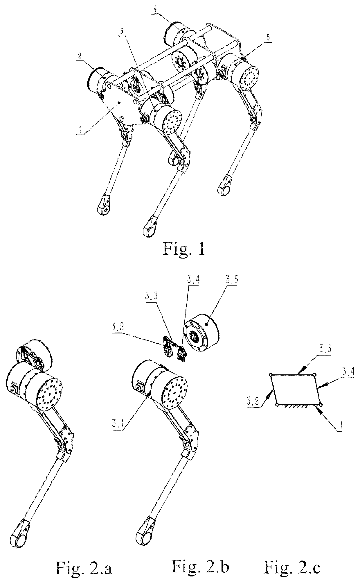
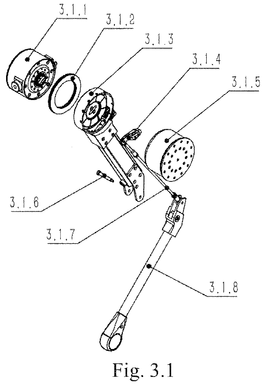
[0017]The present invention consists essentially of a body and four separate leg modules, and each leg module is comprised of a thigh motor assembly, a calf motor assembly, a hip joint motor assembly and an associated linkage and fixing base of the hip joint motor assembly. The hip joint motor drives the thigh and calf assembly through a parallelogram mechanism, the thigh motor assembly directly drives the thigh rod assembly, and the calf motor assembly drives the calf assembly through an anti-parallelogram mechanism. When a thigh of the robot is impacted laterally because the robot falls laterally, the anti-fall motor protection plate at the outermost side of the thigh disperses and concentrates the external impact force on the circumference of the calf motor end cover, and further directly transfers the external impact force to the calf motor housing, and the external impact force acting on the

Problems solved by technology

However, due to the limitation of the current process and structure of motors and reducers, the existing four-legged robot electrically drives joints, has a large size, a complicated structure, a large weight, and can hardly withstand a large axial impact force, resulting, in a damage.
On the other hand, a transmission mechanism currently adopted by many legged robots has its leg drive links directly exposed to the outside and thus is easily damaged by collision f

Method used


Image

  • Leg power system structure of electrically driven four-legged robot
  • Leg power system structure of electrically driven four-legged robot
  • Leg power system structure of electrically driven four-legged robot

Examples


Example

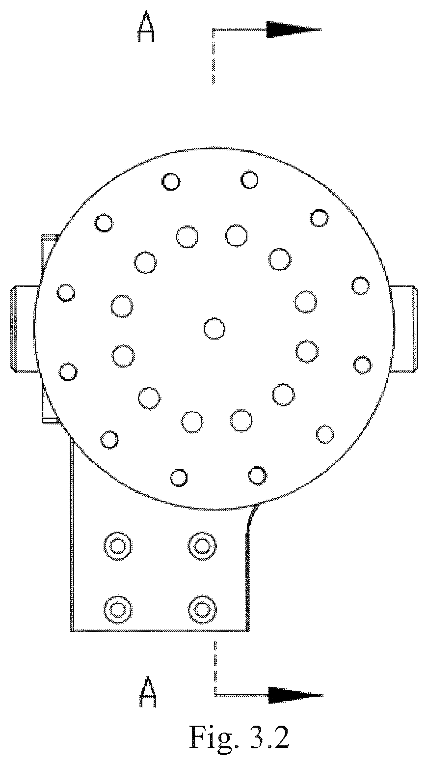
[0037]Body 1; first leg module 2; second leg module 3; third leg module 4; fourth leg module 5; thigh and calf assembly 3.1; side-lift hip joint driving crank 3.2; side-lift hip joint link 3.3; side-lift hip joint driven crank 3.4; side-lift hip joint motor assembly 3.5; thigh motor assembly 3.1.1; thrust bearing 3.1.2; thigh rod assembly 3.1.3; calf driving crank 3.1.4; calf motor assembly 3.1.5; calf rotation pin 3.1.6; calf drive link 3.1.7; calf assembly 3.1.8; side-lift hip joint motor rear end cover assembly 3.5.1; side-lift hip joint permanent magnet brushless motor 3.5.2; side-lift hip joint motor housing 3.5.3; side-lift hip joint motor planetary gear reducer 3.5.4; side-lift hip joint motor front end cover 3.5.5; thigh motor rear end cover assembly 3.1.1.1; thigh permanent magnet brushless motor 3.1.1.2; thigh motor housing 3.1.1.3; first hip joint rotation pin 3.1.1.4; thigh motor planetary gear reducer 3.1.1.5; thigh motor front end cover 3.1.1.6; second hip joint rotati...


PUM


Abstract

A leg structure of a quadruped robot includes a body and four separate leg modules. Each leg module includes a thigh motor assembly, a calf motor assembly, a hip joint motor assembly and an associated linkage and fixing base of the hip joint motor assembly. The hip joint motor drives the thigh and calf assembly through a parallelogram mechanism, the thigh motor assembly directly drives the thigh rod assembly, and the calf motor assembly drives the calf assembly through an anti-parallelogram mechanism. The joint motor assemblies are independent of each other and all the motor assemblies are modularized; the thigh and calf motor assemblies have a good ability to prevent external impact, and the joints on the robot body, formed by using the motor assemblies, have a large working space, thus ensuring the movement flexibility of the robot.

Description

TECHNICAL FIELD[0001]The present invention relates to a leg structure of a quadruped robot, and in particular to a leg power system structure of an electrically driven four-legged robot.BACKGROUND ART[0002]Compared with wheeled robots, legged robots have stronger terrain adaptability and can flexibly move in complex terrain environments. Research institutes at home and abroad are striving to advance the process of four-legged robots. At present, a pure motor-driven power system has gradually become the mainstream power system of small and medium-sized four-legged robots due to its many advantages such as low noise, high reliability and low cost. However, due to the limitation of the current process and structure of motors and reducers, the existing four-legged robot electrically drives joints, has a large size, a complicated structure, a large weight, and can hardly withstand a large axial impact force, resulting, in a damage. On the other hand, a transmission mechanism currently ad...

Claims


Application Information

Patent Timeline
IPC IPC(8): B25J9/12B62D57/032B25J9/10B25J19/00B25J17/00
CPCB25J19/0075B25J9/106B62D57/032B25J9/108B25J9/104B25J9/102B25J19/0054B25J19/0004B25J17/00B25J9/126B60K1/02B60K7/0007B60K2007/0046B60K17/356
Inventor WANG, XINGXINGYANG, ZHIYU
Owner HZ UNITREE TECHNOLOGY CO LTD
Learn More