Coil component and filter circuit including same
a filter circuit and coil technology, applied in the direction of impedence networks, transformers/inductance details, inductances, etc., can solve the problem of widening the frequency band where the attenuation effect is achieved
- Summary
- Abstract
- Description
- Claims
- Application Information
AI Technical Summary
Benefits of technology
Problems solved by technology
Method used
Image


Examples
embodiment 1
Preferred Embodiment 1
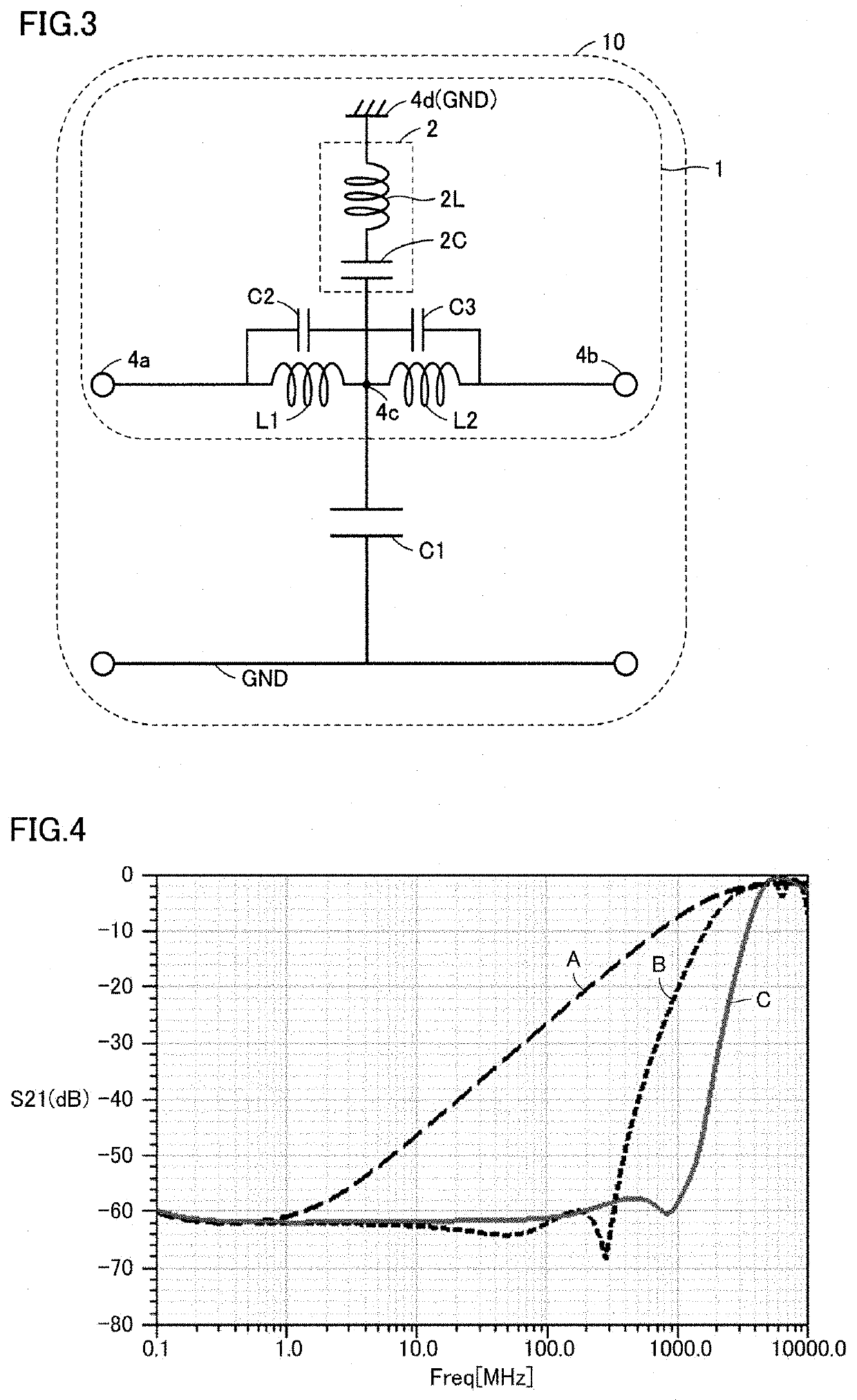
[0022]First, a coil component according to a preferred embodiment 1 of the present invention and a filter circuit including the coil component will be described. FIGS. 1A and 1B are a perspective view and a side view of a coil component according to preferred embodiment 1 of the present invention. FIGS. 2A to 2E are exploded plan views illustrating the configuration of the coil component according to preferred embodiment 1 of the present invention. FIG. 3 is a circuit diagram of a filter circuit that includes the coil component according to preferred embodiment 1 of present invention.
[0023]A filter circuit 10 is preferably, for example, an EMI removal filter and is a third order T-type LC filter circuit. A coil component 1 is used in the filter circuit 10. In preferred embodiment 1, it is described that, for example, a third-order T-type LC filter circuit is used as the configuration of the filter circuit 10, but the present invention can be similarly applied t...
embodiment 2
Preferred Embodiment 2
[0060]In the coil component 1 according to preferred embodiment 1 of the present invention, one electrode 2 is provided at a position adjacent to or in the vicinity of a portion of each of the coils L1 and L2 as illustrated in FIGS. 1A and 1B, but a plurality of such electrodes may instead be provided. FIGS. 8A and 8B are a perspective view and a side view of a coil component according to a preferred embodiment 2 of the present invention. FIGS. 9A to 9G are exploded plan views illustrating the configuration of the coil component according to preferred embodiment 2 of the present invention. The circuit configuration of a filter circuit including the coil component according to preferred embodiment 2 is the same or substantially the same as the circuit configuration illustrated in FIG. 3, and therefore, detailed description thereof will not be repeated.
[0061]As illustrated in FIGS. 8A and 8B, a coil component 1a is provided by stacking a plurality of substrates o...
embodiment 3
Preferred Embodiment 3
[0074]The configurations of only the coil components 1 and 1a have been described in preferred embodiments 1 and 2 of the present invention. In a preferred embodiment 3 of the present invention, the configuration of a filter circuit in which such a coil component is integrated with a capacitor will be described. FIG. 10 is a side view of a filter circuit according to preferred embodiment 3 of the present invention. The circuit configuration of a filter circuit according to preferred embodiment 3 is the same or substantially the same as the circuit configuration illustrated in FIG. 3, and therefore detailed description thereof will not be repeated. In addition, the coil component used in the filter circuit is the same or substantially the same as the coil component 1 or 1a described in preferred embodiments 1 and 2, and therefore detailed description thereof will not be repeated.
[0075]In the filter circuit 10 illustrated in FIG. 10, the coil component 1 is provi...
PUM
| Property | Measurement | Unit |
|---|---|---|
| capacitance | aaaaa | aaaaa |
| frequencies | aaaaa | aaaaa |
| frequencies | aaaaa | aaaaa |
Abstract
Description
Claims
Application Information
 - R&D
- Intellectual Property
- Life Sciences
- Materials
- Tech Scout
- Unparalleled Data Quality
- Higher Quality Content
- 60% Fewer Hallucinations
Browse by: Latest US Patents, China's latest patents, Technical Efficacy Thesaurus, Application Domain, Technology Topic, Popular Technical Reports.
© 2025 PatSnap. All rights reserved.Legal|Privacy policy|Modern Slavery Act Transparency Statement|Sitemap|About US| Contact US: help@patsnap.com