Geothermal Source On-Site Power Generation Plant With Computing Facility and Method

a technology of geothermal power generation and computing facilities, applied in the direction of machines/engines, lighting and heating apparatus, heating types, etc., can solve the problems of economic stranding of low-heat geothermal water wells, low economic value, and low utility value of low-temperature geothermal resources, so as to achieve low economic value, low cost, and clean electricity

Active Publication Date: 2020-09-03
EAGLE QUILL IP GRP LLC
View PDF0 Cites 0 Cited by
  • Summary
  • Abstract
  • Description
  • Claims
  • Application Information

AI Technical Summary

Benefits of technology

The patent describes a method for generating electricity from low temperature geothermal sources, such as warm water aquifers or hot springs, for use on-site at electronic signals processing facilities. This eliminates the need for costly and inefficient transportation of the electricity to remote locations. The method utilizes a hydraulic heat engine and a low temperature geothermal resource to generate electricity, which is then used on-site for computing or other non-computing related uses. The approach takes advantage of the fact that data transmission systems are more cost-effective and efficient than power transmission systems. The method is economically viable, as the low-heat geothermal resources are considered to be economically stranded. The use of on-site power generation with electronic signals processing facilities reduces greenhouse gas emissions and environmental impact. The method also utilizes immersion cooling technologies, which require less space and electricity, resulting in a lower environmental impact.

Problems solved by technology

Low temperature geothermal wells or other low temperature geothermal resources (usually less than 210° F.) have typically been limited to uses such as space heating and domestic water heating for residential, greenhouse, or industrial buildings, provided a need for these uses exists within a reasonable proximity.
In other words, low temperature geothermal resources have historically had very limited utility and low economic value.
Although there are other types of heat engines that are capable of generating electricity using water at temperatures similar to those available from low-heat geothermal water wells, they operate at considerably lower efficiencies and therefore produce higher cost electricity.
Hence, low-heat geothermal water wells are considered to be economically stranded.

Method used


Image

  • Geothermal Source On-Site Power Generation Plant With Computing Facility and Method
  • Geothermal Source On-Site Power Generation Plant With Computing Facility and Method
  • Geothermal Source On-Site Power Generation Plant With Computing Facility and Method

Examples


Embodiment Construction

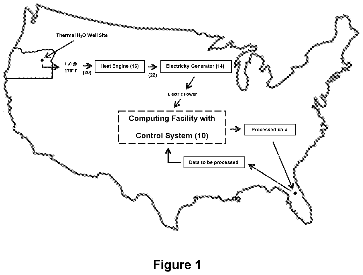
.” The claims that follow define the systems and methods provided herein, distinguishing them from the prior art. However, without limiting the scope of our electronic signals processing facility and method as expressed by these claims, in general terms, some, but not necessarily all, of their features are:[0019]1. A site (a physical area) with geothermal resources in the form of low temperature (typically 140 degrees F. to 212 degrees F. or hotter) water.[0020]2. A well drilled on the site to a depth which taps into a hot water aquifer and produces adequate hot water flow of an adequate temperature to serve the energy requirement of the computing or other facility, or an intake pipe placed in a hot lake, hot spring or other source of geo-thermally heated water which is capable of withdrawing adequate hot water flow of an adequate temperature to serve the energy requirement of the computing or other facility.[0021]3. A device (such as a submersible or other pump) which moves hot wat...


PUM


Abstract

An electronic signals processing facility which includes a site with a geothermal hot water resource which feeds hot water to an on-site heat engine that drives an on-site electricity generator which provides electrical power to an array of microprocessors, located in an enclosure structure, that processes data transmitted from a remote location at high speeds. The processed data is transmitted back to the remote locations at high speeds.

Description

INCORPORATION BY REFERENCE[0001]Any and all U.S. patents, U.S. patent applications, and other documents, hard copy or electronic, cited or referred to in this application are incorporated herein by reference and made a part of this application.REFERENCES CITED - U.S PATENT DOCUMENTSU.S. Pat. No. 4,747,271 AMay 1988FischerU.S. Pat. No. 5,899,067 AMay 1999HagemanU.S. Pat. No. 9,869,274 B2January 2018FuhrmanDefinitions[0002]The words “comprising,”“having,”“holding,”“containing,” and “including,” and other forms thereof, are intended to be equivalent in meaning and be open ended in that an item or items following any one of these words is not meant to be an exhaustive listing of such item or items, or meant to be limited to only the listed item or items.BACKGROUND[0003]Electronic signals processing and data processing facilities, because they use a large amount of electricity, are dependent upon adequate power supply. Such facilities may be and are hindered or constrained by the need fo...

Claims


Application Information

Patent Timeline
Patent Type & Authority Applications(United States)
IPC IPC(8): F03G7/04F24D3/18
CPCF24D3/18F24D2200/11F24D2200/12F03G7/04Y02E10/10Y02B10/40Y02B30/12
Inventor STEWART, GREGORY B.BUNTING, VINCENT B.TUCKER, GLENN T,RAPLEE, GREGORY B.HAGEMAN, BRIAN
Owner EAGLE QUILL IP GRP LLC
Why Eureka
Try Eureka