Gas supplying unit of substrate treating apparatus

Active Publication Date: 2020-09-03
SEMES CO LTD
View PDF0 Cites 0 Cited by
  • Summary
  • Abstract
  • Description
  • Claims
  • Application Information

AI Technical Summary

Benefits of technology

The present invention relates to a substrate treating process, and it involves a gas distribution plate and a shower head. The invention introduces heat transfer members into the gas distribution plate and the shower head to improve process uniformity in the substrate treating process. The close contact between the gas distribution plate and the shower head without any gaps prevents the process gas from reacting with the heat transfer members and avoids the possibility of plasma discharge or incomplete purging of the process gas. Overall, the heat transfer members facilitate the transfer of heat from the shower head to the gas distribution plate, which helps to maintain a uniform temperature across the substrate and improves the quality of the substrate treating process.

Problems solved by technology

However, according to the related art shown in FIG. 1, heat may not transfer well between the gas distribution plate 10 and the shower head 20 due to reasons such as manufacturing tolerance between the gas distribution plate 10 and the shower head 20, deformation by long-time use in a vacuum atmosphere, and a difference in coefficient of thermal expansion.
Accordingly, as the process progresses, the temperature of the shower head rapidly increases, and in this case, various problems such as process uniformity may be caused.

Method used


Image

  • Gas supplying unit of substrate treating apparatus
  • Gas supplying unit of substrate treating apparatus
  • Gas supplying unit of substrate treating apparatus

Examples


first embodiment

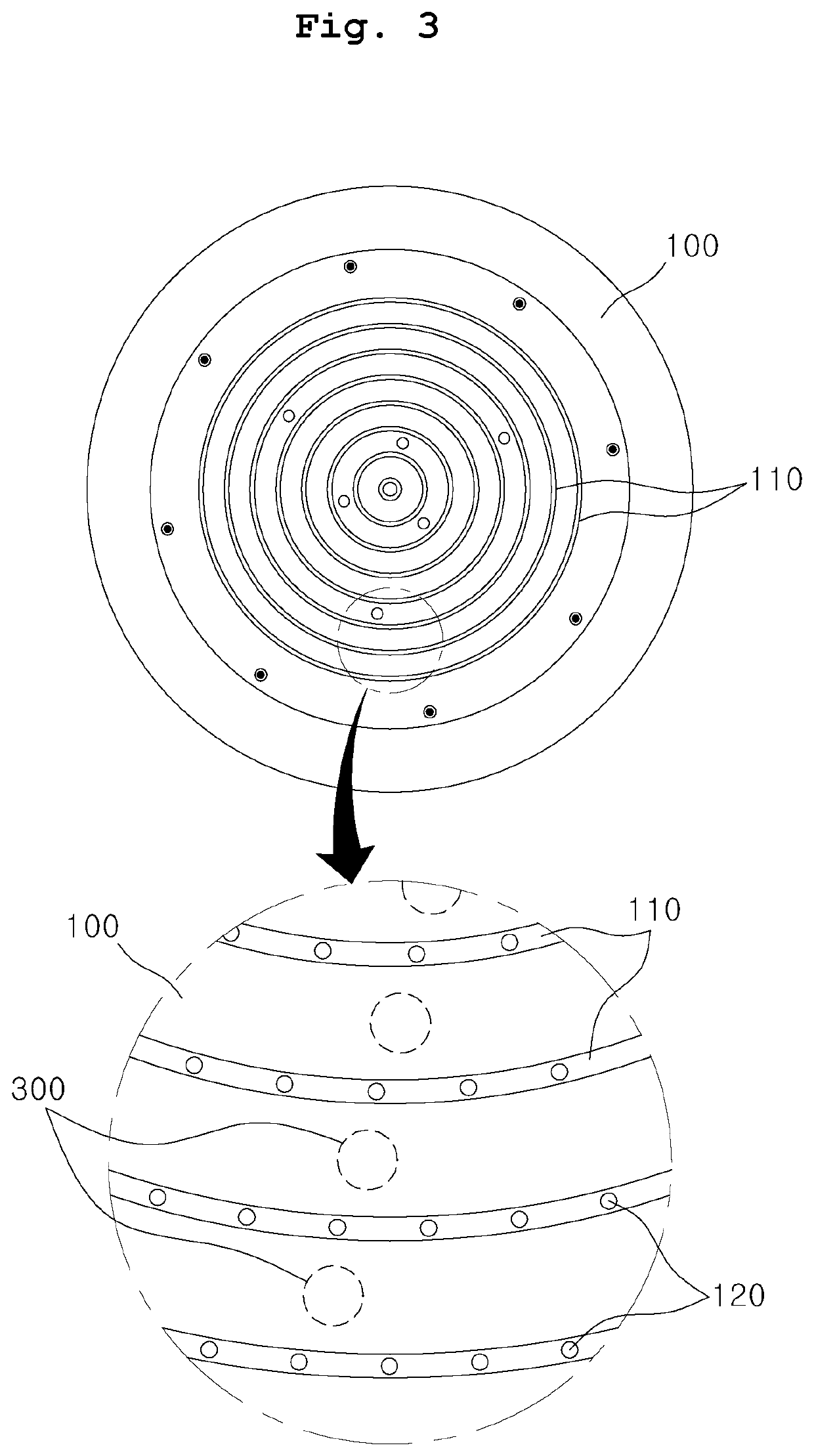
[0041]FIGS. 3 and 4 are views of the gas supplying unit of a substrate treating apparatus according to the present invention.

[0042]Referring to FIGS. 3 and 4, a gas supplying unit of a substrate treating apparatus includes a gas distribution plate 100 and a shower head 200 coupled to the bottom of the gas distribution plate 100.

[0043]The gas distribution plate 100 may be formed in a disc shape having a first surface 101 and a second surface 102 opposite the first surface 101. A plurality of distribution spaces 110 having different diameters is coaxially disposed on the first surface 101 around the center of the gas distribution plate 100. The second surface 102 of the gas distribution plate 100 may be a surface being in close contact with the shower head 200. In an exemplary embodiment, each of the plurality of distribution spaces 110 may be shaped of an annular ring. The plurality of distribution spaces may be positioned at different radii of the gas distribution plate 100. In an e...

second embodiment

[0058]FIG. 5 is a view showing a gas supplying unit of a substrate treating apparatus according to the present invention.

[0059]According to the first embodiment, the upper ends of the heat transfer members 300 may be exposed through the first surface 101 of the gas distribution plate 100. When the upper ends of the heat transfer members 300 are exposed in this way, the heat transfer members 300 may chemically react with a process gas that is supplied to the gas distribution plate 100.

[0060]Accordingly, in the second embodiment, caps 400 may be disposed on the upper ends of the heat transfer members 300, as shown in FIG. 5. The caps 400 may be made of a material that does not generate a chemical reaction with the process gas, for example, synthetic resin.

[0061]Accordingly, exposure of the heat transfer members 300 to the first surface 101 of the gas distribution plate 100 is prevented by the caps 400, and accordingly, reaction of the heat transfer members 300 with the process gas can...

third embodiment

[0062]FIG. 6 is a view showing a gas supplying unit of a substrate treating apparatus according to the present invention.

[0063]Referring to FIG. 6, cores 500 may be disposed in the heat transfer members 300. That is, the heat transfer members 300 are formed in hollow tube shapes and the cores 500 are inserted in the heat transfer members 300. The cores 500 may be a substance having thermal conductivity higher than that of the heat transfer members 300. For example, the cores 500 may be metal or ceramic.

[0064]Since the cores 500 having relatively high thermal conductivity are inserted in the heat transfer members 300, heat of the shower head can more quickly transfer to the gas distribution plate 100.

[0065]Further, since the heat transfer members 300 are made of an elastic material, the cores 500 can be made of a material having sufficient strength. Accordingly, it is possible to absorb the difference of thermal expansion between the gas distribution plate 100 and the shower head 200...


PUM

PropertyMeasurementUnit
Lengthaaaaaaaaaa
Lengthaaaaaaaaaa
Thicknessaaaaaaaaaa

Abstract

A gas supplying unit of a substrate treating apparatus is proposed. The gas supplying unit includes: a gas distribution plate having a first surface and a second surface opposite the first surface, and having first gas supply holes formed through the first surface and the second surface; a shower head having a third surface being in close contact with the second surface and a fourth surface opposite the third surface, and having second gas supply holes formed through the third surface and the fourth surface to be connected to the first gas supply holes; and heat transfer members having first ends inserted in at least one of the gas distribution plate and the shower head and second ends being in contact with any one of the shower head and the gas distribution plate.

Description

CROSS REFERENCE TO RELATED APPLICATION[0001]The present application claims priority to Korean Patent Application No. 10-2019-0023804, filed Feb. 28, 2019, the entire contents of which is incorporated by reference herein for all purposes.BACKGROUND OF THE INVENTIONField of the Invention[0002]The present invention relates to a substrate treating apparatus and, more particularly to a gas supplying unit of a substrate treating apparatus.Description of the Related Art[0003]Various processes such as photographing, etching, thin film deposition, ion injection, and cleaning are performed to manufacture a semiconductor device. A substrate treating apparatus that uses a process gas is used in the etching, thin film deposition, and cleaning of the processes.[0004]The process gas should be uniformly supplied to the entire area of a substrate and may be supplied through a gas supplying unit for uniform supply to each region.[0005]The gas supplying unit is usually provided in a structure in which...

Claims


Application Information

Patent Timeline
IPC IPC(8): C23C16/455C23C16/458
CPCC23C16/45565C23C16/4557C23C16/4582H01L21/67017H01L21/67069H01L21/67109H01L21/67098H01L21/02
Inventor SON, HYOUNG KYULEE, JIN HYUN
Owner SEMES CO LTD
Why Eureka
Try Eureka