Thermal integration of thermoelectronic device

Inactive Publication Date: 2012-05-17
THE BOEING CO
View PDF2 Cites 29 Cited by
  • Summary
  • Abstract
  • Description
  • Claims
  • Application Information

AI Technical Summary

Benefits of technology

[0016]In another aspect of the disclosure, a method for thermal integration of a thermoelectric device includes the steps of providing an array of thermoelectric devices, placing a first face sheet in close proximity to, and covering, one side of the array of thermoelectric devices, placing a second face sheet in close proximity to, and covering, an opposing side of the array of thermoelectric devices, providing a first layer of porous material in close proximity to the first face sheet to thereby form an improved thermoelectric component, and positioning the first face sheet adjacent to a heated environment. The method further includes the steps of providing a second layer of porous material in close proximity to the second face sheet, and positioning the second face sheet adjacent to a cooled environment.

Problems solved by technology

Thermoelectric device (TD) are typically thin (e.g., in the order of a couple of millimeters thick), small (e.g., a couple of square centimeters), flat, and brittle.
Accordingly, thermoelectric devices can be difficult to handle individually, especially for applications in vehicles, such as automobiles, aircraft and the like, where the thermoelectric devices can be subject to harsh environmental conditions, such as vibration, constant temperature variations and other harsh conditions.
This can cause relatively large thermal expansion in materials.
Because of thermal gradients and different thermal coefficients of expansion associated with different materials, thermally induced stresses may result.
For a turbine engine having a typical mechanically driven electric generator, an increase in electrical demand results in increased fuel consumption, increased air pollution, and higher exhaust temperatures.
However, such an increase in electrical demand does not result in increased fuel consumption, higher exhaust temperatures, and increased air pollution when using thermoelectric generators.
Against this background, it has been found to be difficult to establish a large temperature gradient across a thermoelectric device in applications where the heat flow is governed by forced convection derived from fluids, such as gases and liquids.
That is, the fluid flow is not normally capable of transferring heat quickly enough to establish a large temperature gradient across a thermoelectric device.
Further, it has been found that thermoelectric devices exhibit fragility and mechanical failure when subjected to thermal and mechanical stresses.
Heat pipes, however, have been found to preclude the use of thermoelectric devices in high temperature installations where there is potential for larger power production.
The challenges associated with the use of heat pipes and pumped coolant loops include the addition of extra or excessive weight, availability of coolant in the system, and reliability (i.e. active components with moving parts).

Method used


Image

  • Thermal integration of thermoelectronic device
  • Thermal integration of thermoelectronic device
  • Thermal integration of thermoelectronic device

Examples


Embodiment Construction

[0027]Embodiments of the present disclosure now will be described more fully hereinafter with reference to the accompanying drawings. However, many different embodiments are contemplated and the present disclosure should not be construed as limited to the embodiments set forth herein; rather, these embodiments are provided so that this disclosure will be thorough and complete and better convey the scope of the disclosure to those skilled in the art.

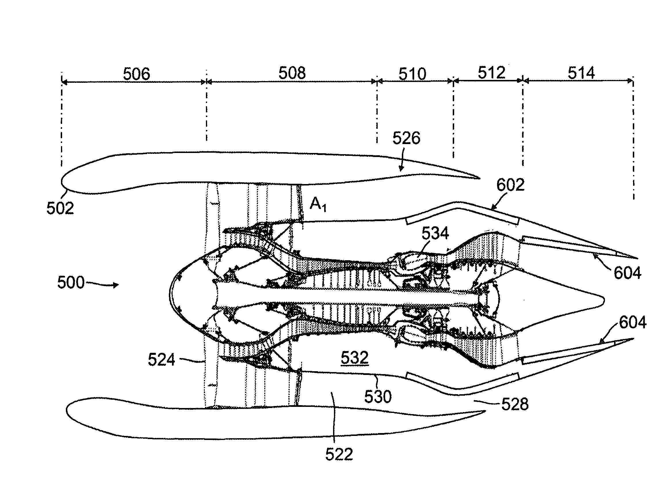
[0028]In its broadest sense, this disclosure presents an improved thermoelectric device having the ability to increase the efficiency of conventional thermoelectric converters. The disclosure also encompasses an engine configuration including an improved thermoelectric assembly, comprising an array of such devices, disposed in a strategically located environment in the engine between hot and cold sources of temperature.

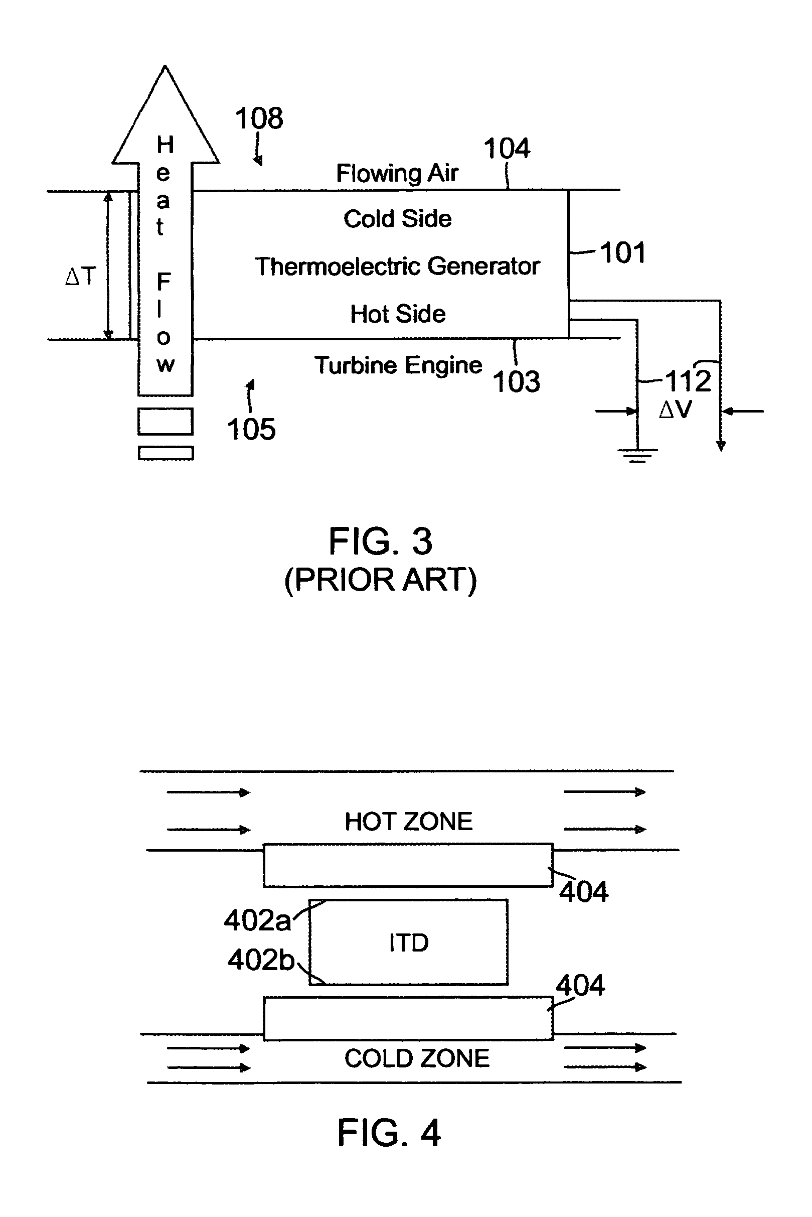
[0029]FIG. 4 shows the improved thermoelectric device ITD according to the present disclosure. In general, each, or both,...


PUM


Abstract

Disclosed is an improved thermoelectric component, a method for thermal integration of the improved thermoelectric component in an environment having thermally distinct zones, and a thermoelectric generation system. In general, the thermoelectric component includes a thermoelectric device having opposing surfaces for arrangement in comparatively hot and cold environments, and an extended surface mounted in close proximity to at least one of the opposing surfaces, the extended surface being a layer of porous material having at least a portion immersed in at least one of the hot or cold environments.

Description

FIELD OF THE DISCLOSURE[0001]The present disclosure relates generally to thermoelectric devices, and more particularly to an improved thermoelectric device and arrangements of thermoelectric devices for generating electricity through convective heat transfer from fluid streams.[0002]Combustion turbine / systems are widely used for power generation. Combustion turbines, also known as gas turbine engines, are known to utilize fuel sources such as natural gas, petroleum, or finely divided, particulate material. Gas-fueled combustion turbine / generator systems have become a particularly attractive way of generating electrical energy because they may be more rapidly brought to an operational state than other types of generating systems.[0003]Gas turbine engines typically include an air intake side and a heat exhaust side. Air is forced into the combustion chamber by a compressor, which is typically formed from a plurality of fan blades within a wheel. Injectors introduce fuel into the combu...

Claims


Application Information

Patent Timeline
IPC IPC(8): H01L35/30
CPCF01D5/284F02C6/18Y02T50/673H01L35/30F02K1/82Y02T50/60H10N10/13
Inventor STOIA, MICHAEL F.KWOK, DAVID W.HUANG, JAMES P.
Owner THE BOEING CO
Why Eureka
Try Eureka