
Methods for Additively Manufacturing Components with Reduced Build Failures Caused by Temperature Variations

Active Publication Date: 2020-08-13
GENERAL ELECTRIC CO
View PDF0 Cites 1 Cited by
  • Summary
  • Abstract
  • Description
  • Claims
  • Application Information

AI Technical Summary

Benefits of technology

This patent is about a method for 3D printing a component by layering material onto a platform using a laser beam. The method includes creating a geometry of the component and controlling the laser beam to melt and fuse the material accordingly. The process is paused when there is a significant change in the surface area to allow the material to cool and prevent build failures in the final component. The technical effect of this method is to improve the accuracy and quality of 3D printing components.

Problems solved by technology

Parts built via DMLM typically have intricate geometries; therefore, heat constants throughout the volume of the part often vary due to geometric changes in the part.
As the heat added increases, the build quality of the part may be compromised, e.g. due to shrinkage, uneven builds between the layers, varying densities, color discrepancies, poor surface quality, etc.

Method used


Image

  • Methods for Additively Manufacturing Components with Reduced Build Failures Caused by Temperature Variations
  • Methods for Additively Manufacturing Components with Reduced Build Failures Caused by Temperature Variations
  • Methods for Additively Manufacturing Components with Reduced Build Failures Caused by Temperature Variations

Examples


Embodiment Construction

[0015]Reference will now be made in detail to present embodiments of the invention, one or more examples of which are illustrated in the accompanying drawings. The detailed description uses numerical and letter designations to refer to features in the drawings. Like or similar designations in the drawings and description have been used to refer to like or similar parts of the invention. As used herein, the terms “first,”“second,” and “third” may be used interchangeably to distinguish one component from another and are not intended to signify location or importance of the individual components. In addition, as used herein, terms of approximation, such as “approximately,”“substantially,” or “about,” refer to being within a ten percent margin of error.

[0016]As used herein, the terms “additively manufactured,”“additive manufacturing techniques or processes” or similar generally refer to manufacturing processes wherein successive layers of material(s) are provided on each other to “build...


PUM

PropertyMeasurementUnit
Temperatureaaaaaaaaaa
Sizeaaaaaaaaaa
Volumeaaaaaaaaaa

Abstract

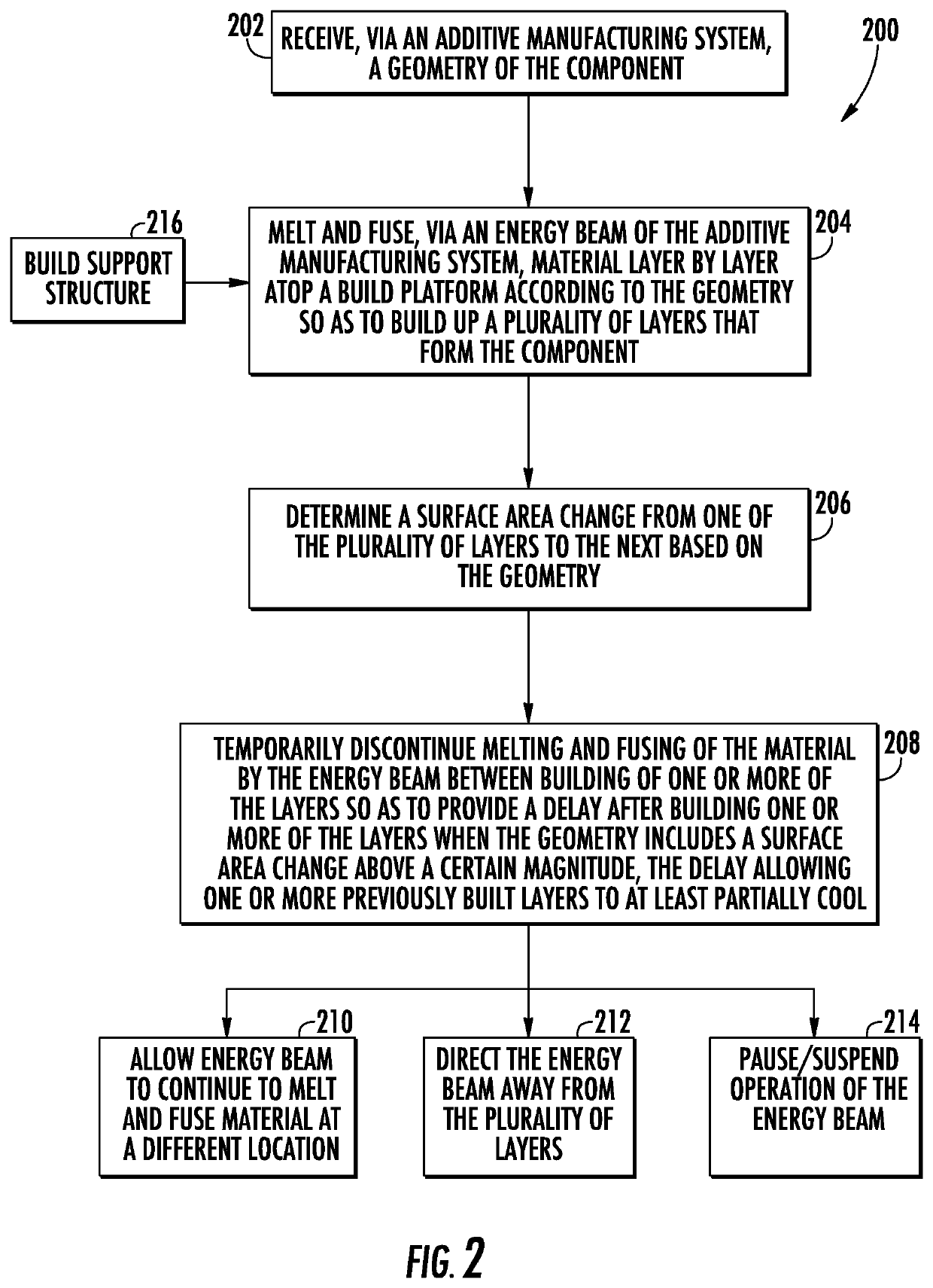
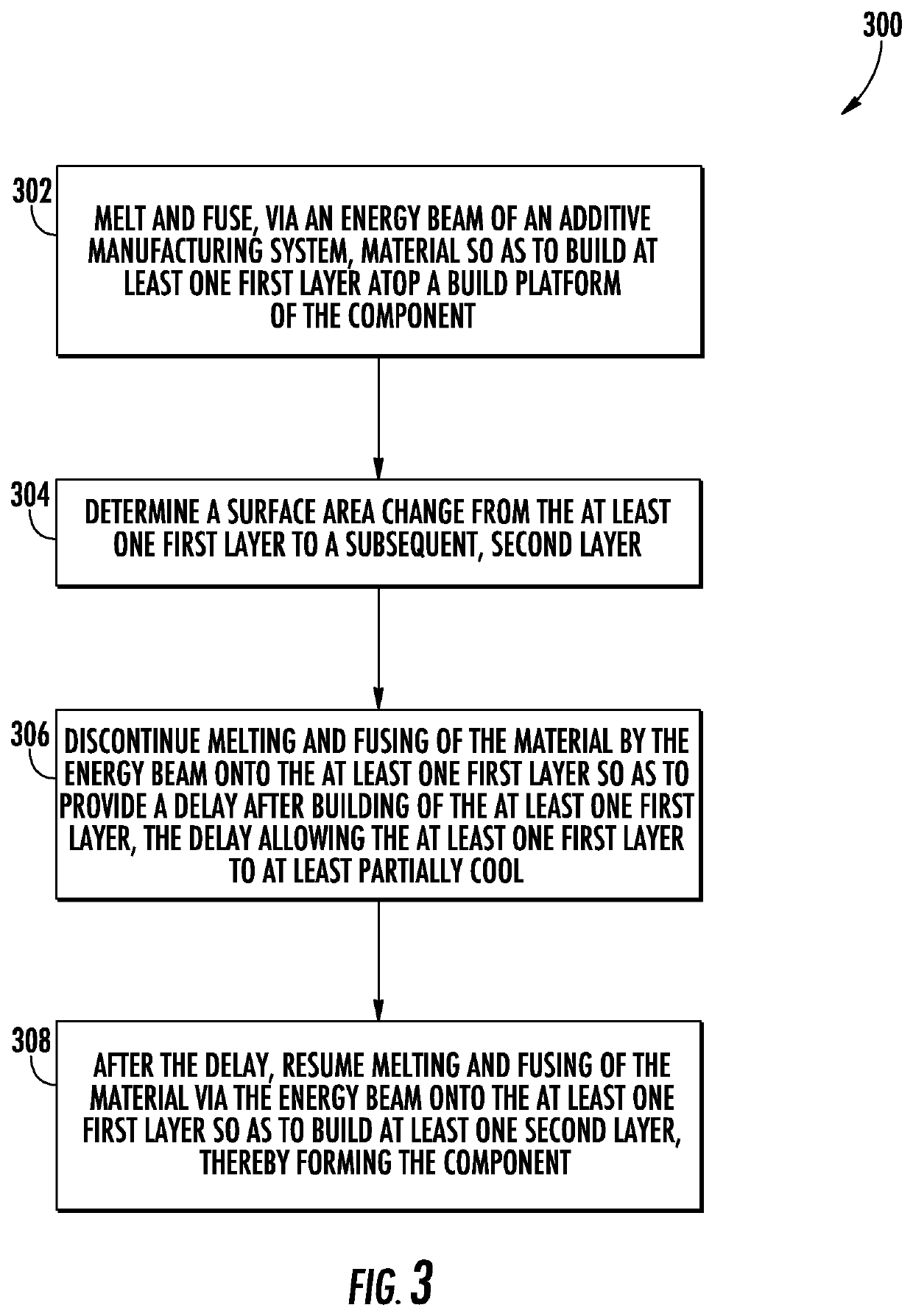
A method for additively manufacturing a component includes receiving, via an additive manufacturing system, a geometry of the component and melting and fusing, via an energy beam of the additive manufacturing system, material layer by layer atop a build platform according to the geometry so as to build up a plurality of layers that form the component. The method also includes determining a surface area change from one of the plurality of layers to the next based on the geometry. Further, the method includes temporarily discontinuing melting and fusing of the material by the energy beam between building of one or more of the plurality of layers so as to provide a delay after building one or more of the plurality of layers when the surface area change is above a predetermined threshold. As such, the delay allows for one or more previously built layers to at least partially cool so as to eliminate and / or reduce build failures from occurring in the final component.

Description

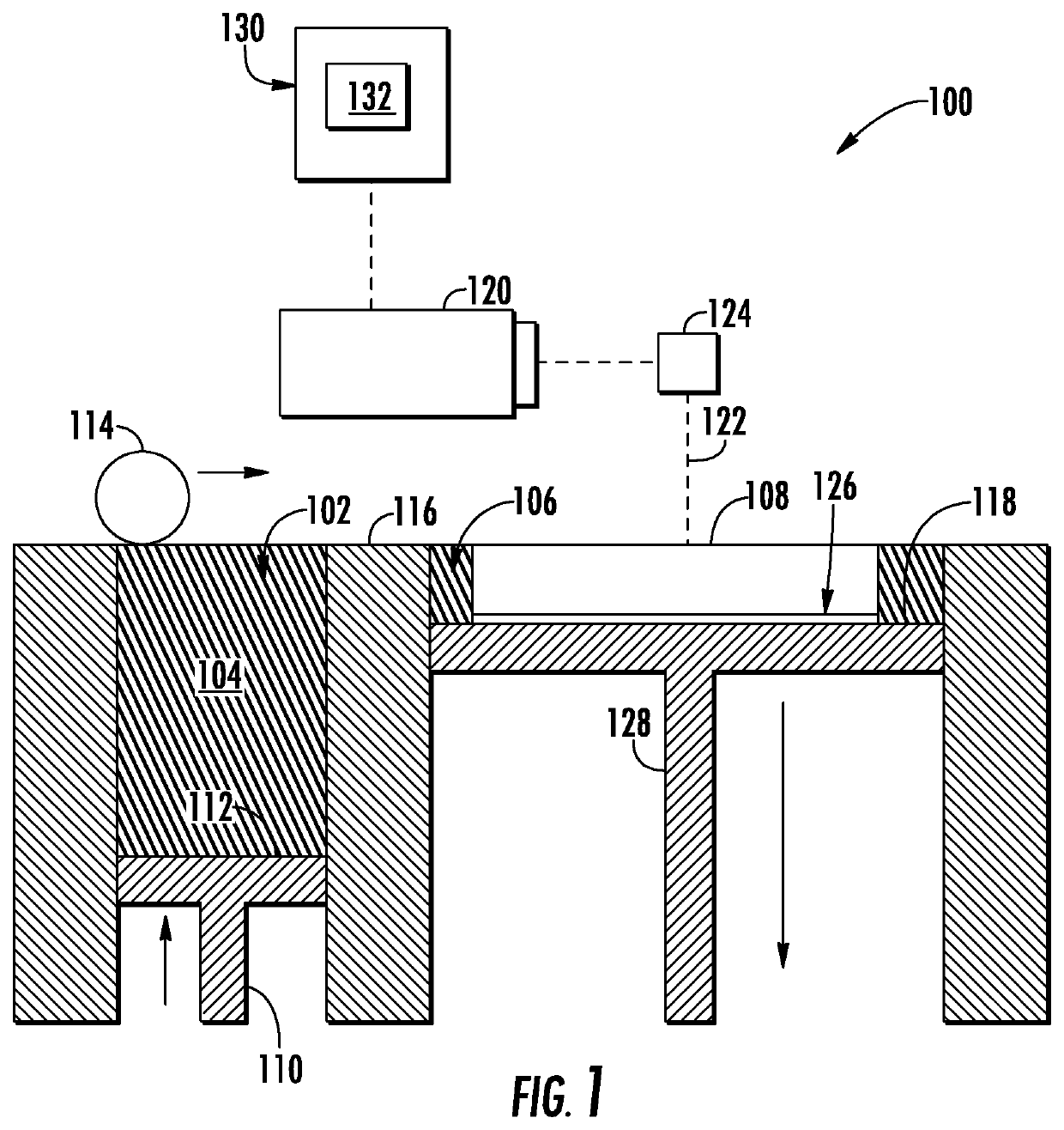
FIELD[0001]The present disclosure relates generally to additively manufacturing and more particularly to methods for additively manufacturing components so as to reduce build failures in the final component caused by temperature variations during the build process.BACKGROUND[0002]Additive manufacturing (AM) processes generally involve the buildup of one or more materials to make a net or near net shape (NNS) object, in contrast to subtractive manufacturing methods. For example, during a particular type of AM process referred to as direct metal laser sintering (DMLS) or direct metal laser melting (DMLM), an apparatus builds objects in a layer-by-layer manner by sintering or melting a powder material using an energy beam. The powder to be melted by the energy beam is spread evenly over a powder bed on a build platform, and the energy beam sinters or melts a cross sectional layer of the object being built under control of an irradiation emission directing device. The build platform is ...

Claims


Application Information

Patent Timeline
IPC IPC(8): B22F3/105B33Y10/00B33Y30/00
CPCB22F3/1055B33Y30/00B22F2003/1056B33Y10/00B22F10/00B22F12/67B22F10/66B22F10/28B22F10/47B22F12/63B22F10/64B22F10/85B29C64/153B29C64/194B29C64/393B29C64/40B23K15/0086B23K26/342B33Y50/02Y02P10/25
Inventor UGARTE, JOHNNATTAN TENNESSEEBLOOMBERG, JOHN ERICZHANG, XUEFENGMOORES, JOHN WILLIAMSTEKLI, JUSTIN MICHAELPARASNIS, SAMEER SURENDRAHU, JUN ZHENG
Owner GENERAL ELECTRIC CO
Learn More