
Vacuum cleaner

Active Publication Date: 2020-08-06
MAKITA CORP
View PDF0 Cites 2 Cited by
  • Summary
  • Abstract
  • Description
  • Claims
  • Application Information

AI Technical Summary

Benefits of technology

The patent aims to reduce the noise level of a vacuum cleaner to make it more user-friendly and comfortable for the user. This noise level can be measured objectively using various methods and can be a result of factors such as airflow, vibration, and noise from the motor. The patent seeks to address this issue by proposing various methods and techniques to minimize the noise level and create a quieter vacuum cleaner.

Problems solved by technology

However, when the fan rotates, it generates noise, which is unpleasant for the user.

Method used


Image

  • Vacuum cleaner
  • Vacuum cleaner
  • Vacuum cleaner

Examples


second embodiment

[0162]In the embodiment described above, the sound-absorbing member 30 is provided in the handheld vacuum cleaner 1. However, in another embodiment of the present teachings, the sound-absorbing member 30 may be provided in a canister vacuum cleaner or dust extractor that comprises castors for rolling on the floor.

[0163]FIG. 22 is a drawing that shows a dust extractor / vacuum 1B of a second embodiment of a vacuum cleaner according to the present teachings. The dust extractor / vacuum 1B comprises: a housing 100, which houses the drive unit that comprises the fan and the motor; and castors 101, which movably support the housing 100 on a floor. The motor is driven by the electric current (power) supplied from one or more batteries 5 mounted on a battery-mounting part. The batteries 5 may be stored in a tool box 102, which is connected to the housing 100. The air-exhaust ports 10 are provided in the housing 100. The sound-absorbing member 30, which was explained in the embodiment described...


PUM


Abstract

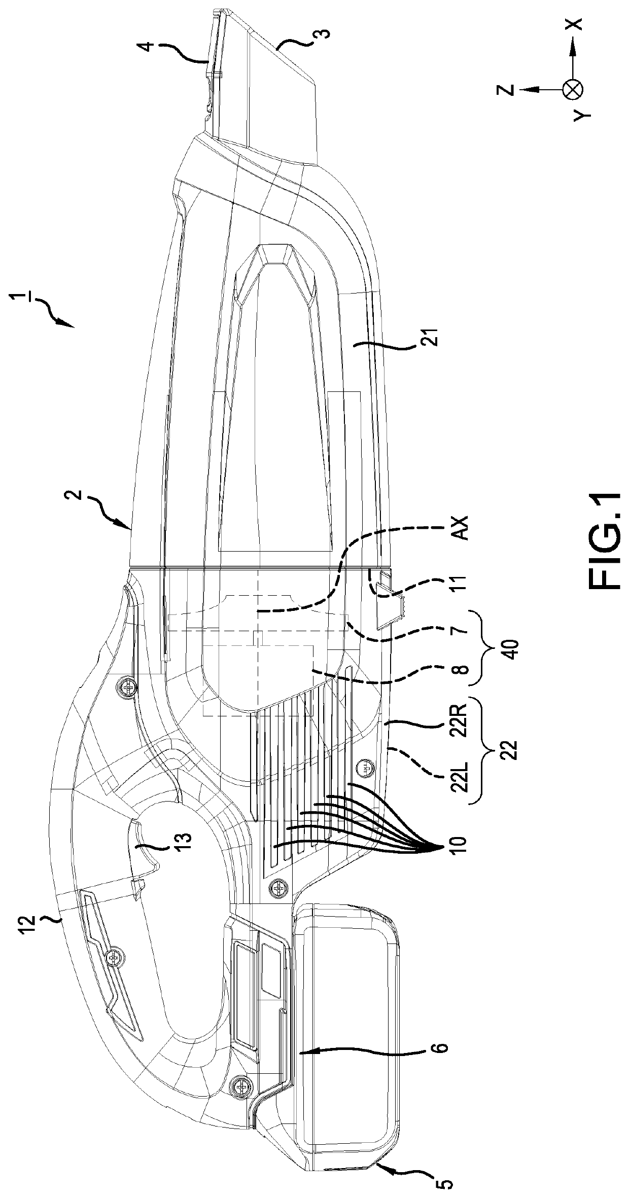
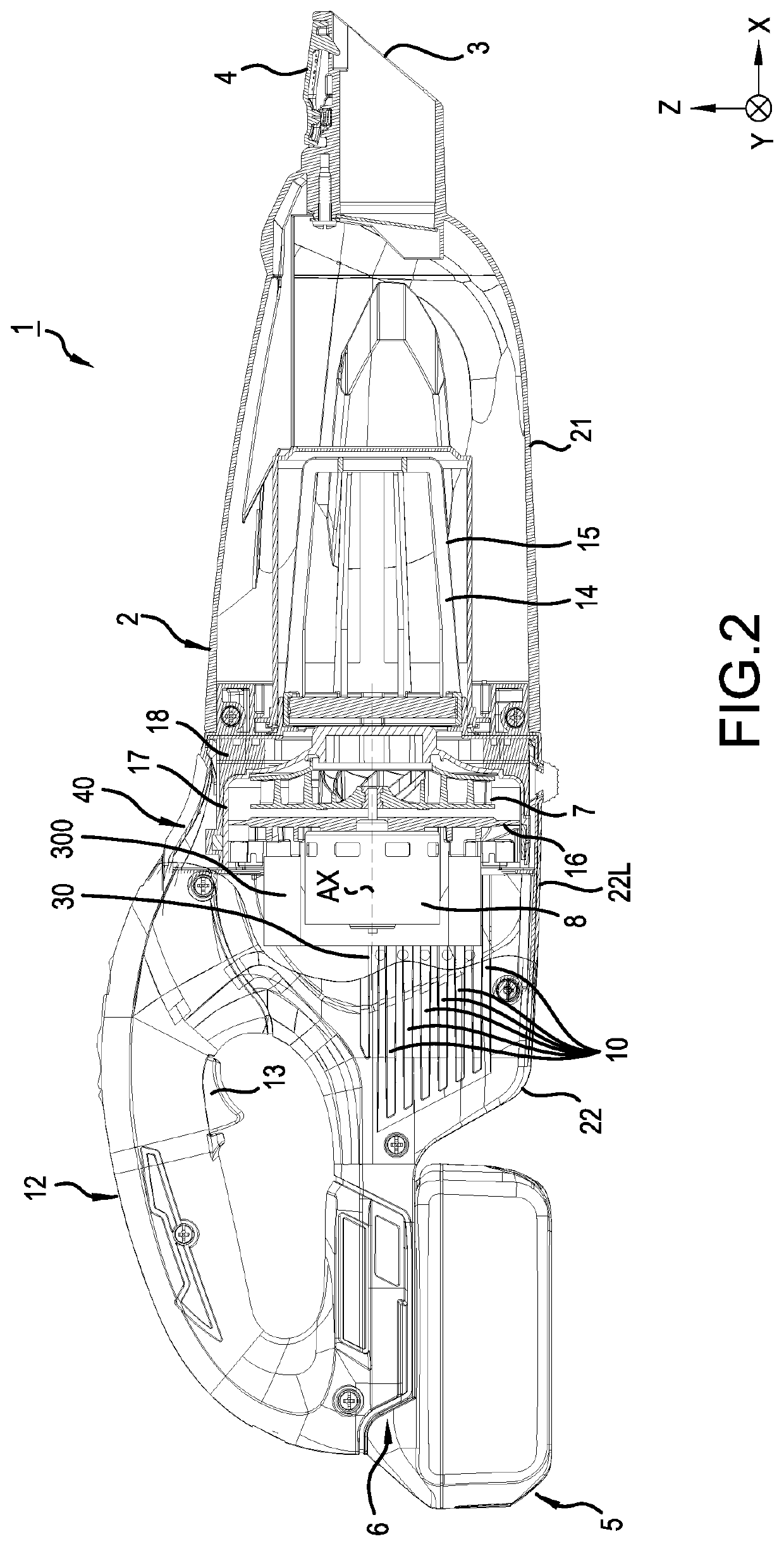
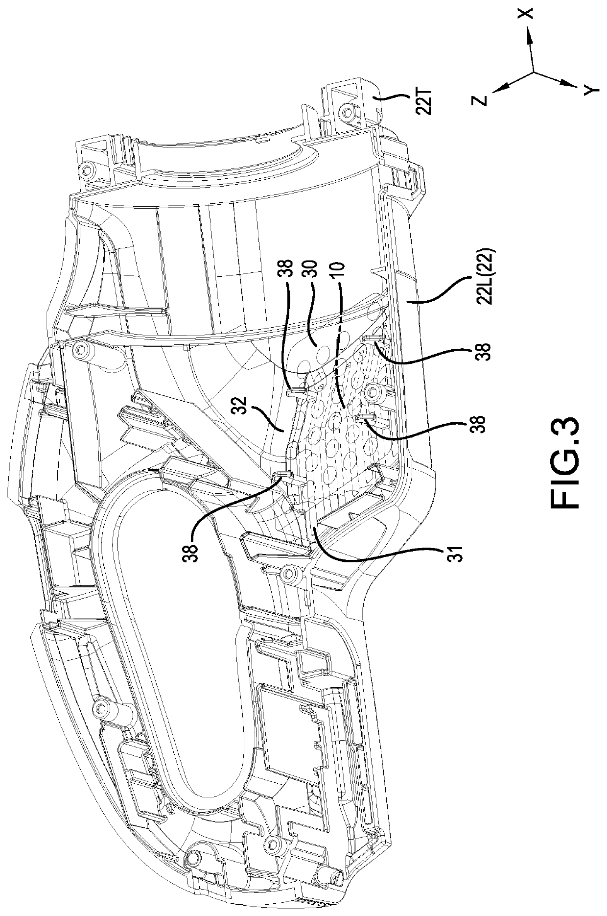
A vacuum cleaner (1; 1B) includes a housing (2; 100) that houses a fan (7) and a motor (8), which generates power that rotates the fan (7); one or more air-exhaust ports (10), which is provided in at least a portion of the housing (2; 100); and a sound-absorbing member (33) having a through hole (33). The sound-absorbing member (33) is disposed in an interior space of the housing (2; 100) so as to face the air-exhaust port(s) (10).

Description

CROSS-REFERENCE[0001]The present application claims priority to Japanese patent application serial number 2019-019872 filed on Feb. 6, 2019, the contents of which are incorporated fully herein by reference.TECHNICAL FIELD[0002]The present invention relates to a vacuum cleaner that is preferably cordless (i.e. powered by a rechargeable battery).BACKGROUND ART[0003]As is disclosed, e.g., in Japanese Laid-open Patent Application 2008-061674, known vacuum cleaners comprise a motor that generates power to rotate a fan. When the fan rotates, air is sucked in, together with dust, debris, etc., via suction ports of the vacuum cleaner. The air sucked in via the suction ports circulates (passes) through an interior space of the vacuum cleaner, which contains a dust filter, and then the filtered air is exhausted via air-exhaust ports.SUMMARY OF THE INVENTION[0004]However, when the fan rotates, it generates noise, which is unpleasant for the user.[0005]It is therefore one non-limiting object of...

Claims


Application Information

Patent Timeline
IPC IPC(8): A47L9/22A47L5/24A47L9/28
CPCA47L5/24A47L9/22A47L9/2884A47L9/0081
Inventor IWAKAMI, JUNICHITAHARA, TAKAYUKI
Owner MAKITA CORP
Learn More