Manufacturing method and manufacturing device for peeling member

Active Publication Date: 2020-07-30
NTN CORP
View PDF0 Cites 0 Cited by
  • Summary
  • Abstract
  • Description
  • Claims
  • Application Information

AI Technical Summary

Benefits of technology

This patent describes a method for making a peeling member by sticking a non-adhesive resin film onto a base material. By using a roller device with a simple structure, the method prevents crumpling and bubbling in the film and ensures a long-lasting peeling member that can withstand usage. The method also allows for easy mass-manufacturing of the peeling member. The film sticking unit includes a plurality of rollers and a moving unit that moves the rollers to stick the film onto the base material. The rollers are sequentially arranged, with some rollers inclined to facilitate folding, and a pair of rollers for finishing interposing the base material from both sides. Overall, this method results in peeling members with consistent quality.

Problems solved by technology

However, in the peeling member obtained by this method, since the fluororesin film is stuck while applying the tensile force, in a case in which the adhesive force is deteriorated in long-time use, the fluororesin film is contracted and therefore a paper might get dirt due to the toner stuck to the expose adhesive.
However, according to this method, it is necessary to use an automatic sticking machine having an expensive and large structure.
Further, in a case in which an uneven shape such as a projection is formed on a stuck surface, the sticking of the fluororesin film is impossible, and therefor design of the peeling member is partially restricted.

Method used


Image

  • Manufacturing method and manufacturing device for peeling member
  • Manufacturing method and manufacturing device for peeling member
  • Manufacturing method and manufacturing device for peeling member

Examples


Embodiment Construction

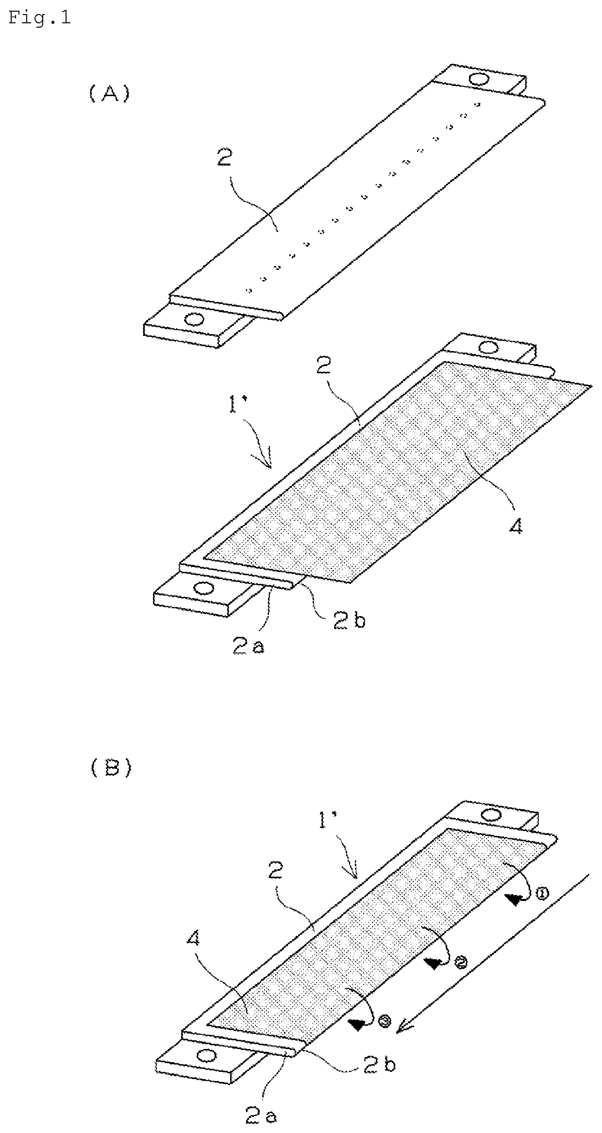
[0028]A manufacturing device for a peeling member of the present invention is formed to manufacture the peeling member provided with a peeling sheet having a base material and a non-adhesive resin film stuck to the base material. In particular, the manufacturing device has a feature in a film sticking unit for sticking the resin film in the peeling sheet. The manufacturing device is used in, for example, a manufacturing method for a peeling member of the present invention described below. FIG. 6 shows the film sticking unit in the manufacturing device. As shown in FIG. 6, a roller device 20 as the film sticking unit is provided for sticking a non-adhesive resin film 4 on both surfaces of a distal end portion 2a of a base material 2, against a base material (composite material 1′) having the non-adhesive resin film 4 stuck to one surface of the base material 2 such that an end portion of the non-adhesive resin film 4 is protruded from a distal end edge 2b of the distal end portion 2a...


PUM

PropertyMeasurementUnit
Angleaaaaaaaaaa
Angleaaaaaaaaaa
Angleaaaaaaaaaa

Abstract

To provide a manufacturing method and a manufacturing device for a peeling member capable of manufacturing the peeling member having less variation in quality and excellent durability for long-time use at a low cost with excellent productivity by a simple structure. The manufacturing method for the peeling member includes sticking a non-adhesive resin film. In sticking the non-adhesive resin film, a distal end edge 2b of a distal end portion 2a of a base material 2 is arranged at a side of an adhesive layer of a non-adhesive resin film 4 such that an end portion of the non-adhesive resin film 4 is protruded from the distal end edge 2b, and then the non-adhesive resin film 4 is stuck on both surfaces of the distal end portion 2a of a base material 2 to wrap the distal end edge 2b of the base material 2 by pressing a plurality rollers 21 to 25 sequentially onto the non-adhesive resin film 4 from an one side end portion toward an another side end portion in a longitudinal direction of the base material 2.

Description

TECHNICAL FIELD[0001]The present invention relates to a manufacturing method and a manufacturing device for a peeling member that peels a paper from a fixing member such as a fixing roller and a fixing belt arranged in an electronic photographic device such as a copying machine and a laser printer.BACKGROUND ART[0002]In an electronic photographic device such as a copying machine and a laser printer, a thermal fixing device that develops an electrostatic latent image, which is formed on a photoreceptor drum, on a paper by using a developing agent such as toner and then fixes the developed image is arranged. The thermal fixing device is provided with a fixing member such as a fixing roller and a fixing belt for fixing the developing agent on a paper by heating and melting and pressing the developing agent.[0003]In the fixing member or a pressing roller that presses the fixing member against a paper, a sheet-like peeling member that peels a paper on which the developing agent is fixed ...

Claims


Application Information

Patent Timeline
IPC IPC(8): G03G15/20B65H37/06B65H5/06
CPCB29C66/81467B29C53/043B65H37/06B29C66/45B65H5/06G03G15/2028Y10T156/1034B29C66/81463B29C63/0034B29C63/042B29L2031/767B65H2301/51214
Inventor HIROSE, KAZUOYANAGAWA, HIROSHI
Owner NTN CORP
Why Eureka
Try Eureka