Wiping assembly for liquid ejection head and ink jet printer

Active Publication Date: 2020-07-02
ROLAND DG CORP
View PDF0 Cites 1 Cited by
  • Summary
  • Abstract
  • Description
  • Claims
  • Application Information

AI Technical Summary

Benefits of technology

The wiping assembly for a liquid ejection head described in this patent allows for both sides of the wiper to be cleaned. This is achieved by designing a protruding portion of the wiper cleaner that moves in the same direction as the wiper in one direction and in the opposite direction in the other. This ensures that both surfaces of the wiper are able to be cleaned. This improves the efficiency and effectiveness of the wiping assembly.

Problems solved by technology

When the liquid that has adhered on the back side surface of the wiping surface is not cleaned and left thereon, the liquid is likely to stick thereon, so that the wiper is hardly bent or a similar inconvenience occurs.

Method used


Image

  • Wiping assembly for liquid ejection head and ink jet printer
  • Wiping assembly for liquid ejection head and ink jet printer
  • Wiping assembly for liquid ejection head and ink jet printer

Examples


Embodiment Construction

[0023]With reference to the attached drawings, ink jet printers according to preferred embodiments will be described below. Note that, as a matter of course, preferred embodiments described herein are not intended to be particularly limiting of the present invention. Also, members and portions that have the same function are denoted by the same reference symbol and redundant description will be omitted or simplified, as appropriate.

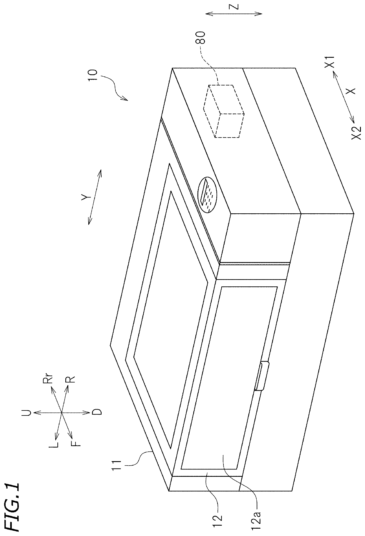
[0024]FIG. 1 is a perspective view of an ink jet printer (which will be hereinafter referred to as a printer) 10 according to a preferred embodiment of the present invention. In the following description, unless specifically stated otherwise, when the printer 10 is viewed from front, a direction away from the printer 10 is a forward direction and a direction approaching the printer 10 is a rearward direction. Left, right, up, and down mean left, right, up, and down when the printer 10 is viewed from front, respectively. Reference symbols F, Rr, L, R, U, a...


PUM


Abstract

A wiping assembly for a liquid ejection head includes a wiper including a first wiper surface facing in a first direction and a second wiper surface facing in a second direction, a wiper cleaner, a mover, and a controller. A protruding portion of the wiper cleaner includes a first cleaning surface facing in the second direction and a second cleaning surface facing in the first direction. The controller controls the mover to move at least one of the wiper and the wiper cleaner in at least one of the first and second directions from a state in which the wiper is located farther in the second direction than the protruding portion to bring the first wiper surface into contact with the first cleaning surface, and to move the at least one of the wiper and the wiper cleaner in at least one of the first and second directions from a state in which the wiper is located farther in the first direction than the protruding portion to bring the second wiper surface into contact with the second cleaning surface.

Description

CROSS REFERENCE TO RELATED APPLICATIONS[0001]This application claims the benefit of priority to Japanese Patent Application No. 2018-244281 filed on Dec. 27, 2018. The entire contents of this application are hereby incorporated herein by reference.BACKGROUND OF THE INVENTION1. Field of the Invention[0002]The present invention relates to a wiping assembly for a liquid ejection head and an ink jet printer including the wiping assembly.2. Description of the Related Art[0003]Conventionally, liquid ejection devices including a wiper that wipes a liquid ejection head and a wiper cleaner that cleans the wiper have been known. For example, Japanese Laid-open Patent Publication No. 2013-188965 discloses an ink jet printer including a wiper that wipes an ink head and a wiper cleaner that cleans the wiper. As described in Japanese Laid-open Patent Publication No. 2013-188965, in general, the wiper is formed of a flexible material. When the wiper is cleaned, the wiper is pressed against a conta...

Claims


Application Information

Patent Timeline
IPC IPC(8): B41J2/165
CPCB41J2/16544B41J2/16541B41J2/16538
Inventor SUGIYAMA, YUICHI
Owner ROLAND DG CORP
Why Eureka
Try Eureka