
Image forming apparatus, image forming system, and deterioration detection method

a technology of image forming and forming apparatus, which is applied in the direction of electrographic process apparatus, thin material processing, instruments, etc., can solve the problems of gate members cannot return to the first attitude, and the energizer provided in the above manner deteriorates, so as to detect the deterioration of energizing for

Active Publication Date: 2020-06-25
KONICA MINOLTA INC
View PDF0 Cites 0 Cited by
  • Summary
  • Abstract
  • Description
  • Claims
  • Application Information

AI Technical Summary

Benefits of technology

The present invention provides an image forming apparatus, system, and methods for detecting the deterioration state of its energy converter and alerting when it needs replacement. This allows for timely maintenance and replacement of the energy converter, ensuring consistent and high-quality printing.

Problems solved by technology

An energizer provided to gate members in the above manner deteriorates over time.
In particular, the energizer constantly applies the energizing force to hold the gate members in the first attitude, and thus the energizing force deteriorates with the passage of time.
When the energizer deteriorates, it takes longer to return from the second attitude to the first attitude after the sheet passes through the gate members, thus resulting in an event in which the gate members cannot return to the first attitude by the time a next sheet is conveyed.
Moreover, when the energizer is deteriorated, another event that the gate members do not return to the original first attitude also occurs.
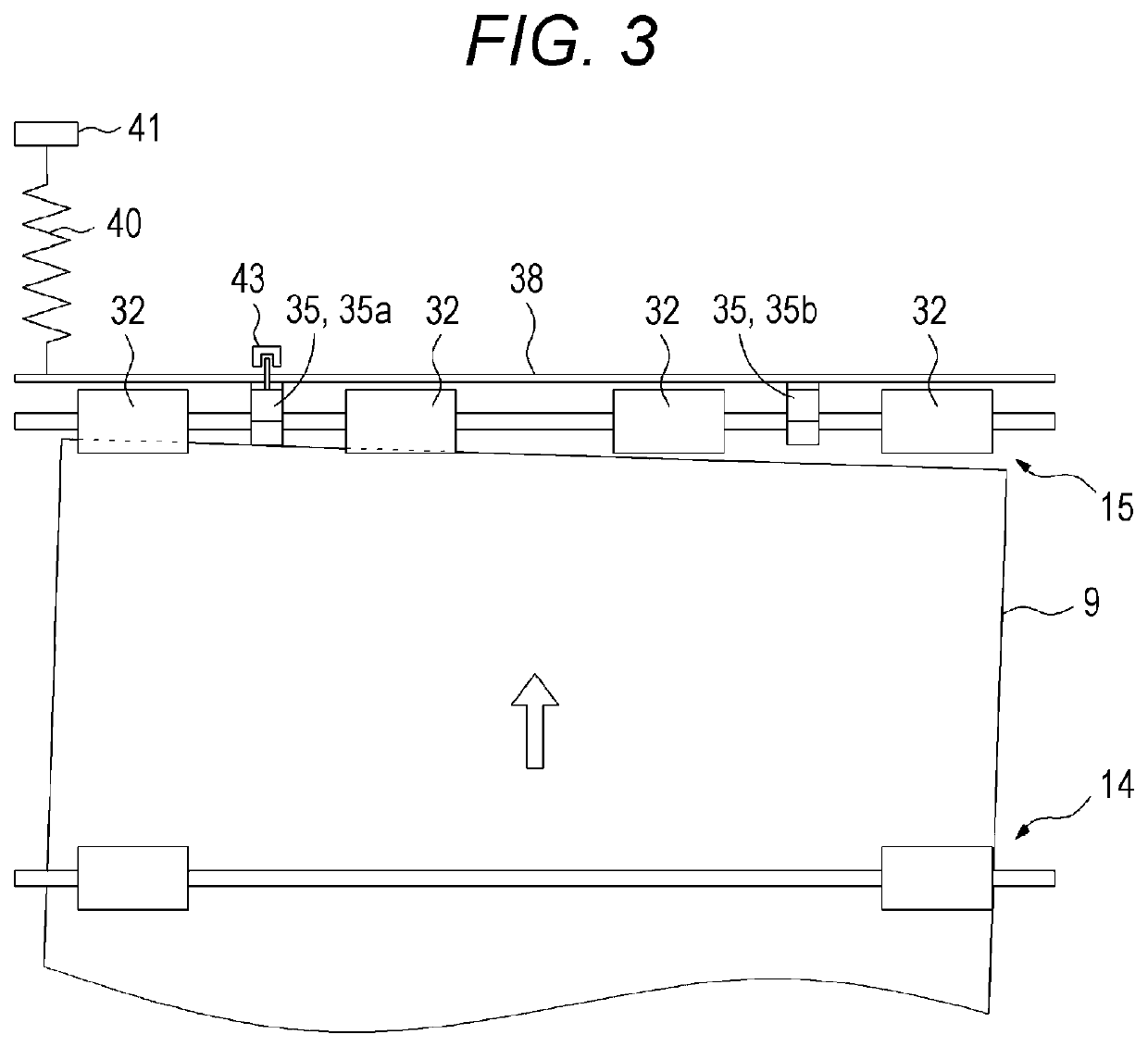
When these events occur, sheet skew correction cannot be performed properly during image formation, thus resulting in a disadvantage that failures such as defective image formation or paper jam occur frequently.
However, since the degree of progress of deterioration of the energizer is affected by the installation environment of the image forming apparatus, the frequency of use by the user, or other factors, it generally varies from apparatus to apparatus.
In this case, the visit of the maintenance person is wasted, thus hindering efficient work.
However, there is no technology for grasping the replacement time of energizer in the related art.

Method used


Image

  • Image forming apparatus, image forming system, and deterioration detection method
  • Image forming apparatus, image forming system, and deterioration detection method
  • Image forming apparatus, image forming system, and deterioration detection method

Examples


Embodiment Construction

[0027]Hereinafter, embodiments of the present invention will be described with reference to the drawings. However, the scope of the invention is not limited to the disclosed embodiments. Note that elements that are common to embodiments described below are denoted by the same reference numeral, and redundant description thereof is omitted.

[0028]Configuration of Image Forming Apparatus

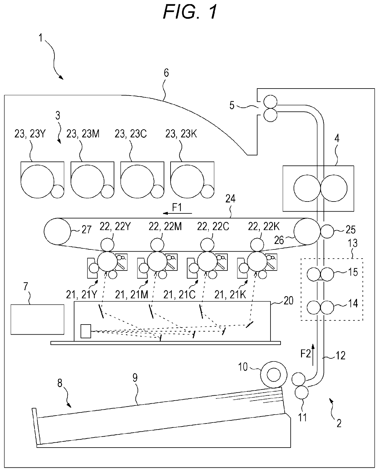
[0029]FIG. 1 is a diagram illustrating a configuration example of an image forming apparatus 1 according to one or more embodiments of the present invention. The image forming apparatus 1 illustrated in FIG. 1 is a printer that forms an image on a sheet 9 such as printing paper by an electrophotographic system, and is capable of forming a color image by a tandem system. The image forming apparatus 1 includes a conveyor 2, an image former 3, and a fixer 4 inside the apparatus main body, and conveys sheets 9 stored in a lower sheet feeding cassette 8 one by one, forms a color image or a monochrome image o...


PUM


Abstract

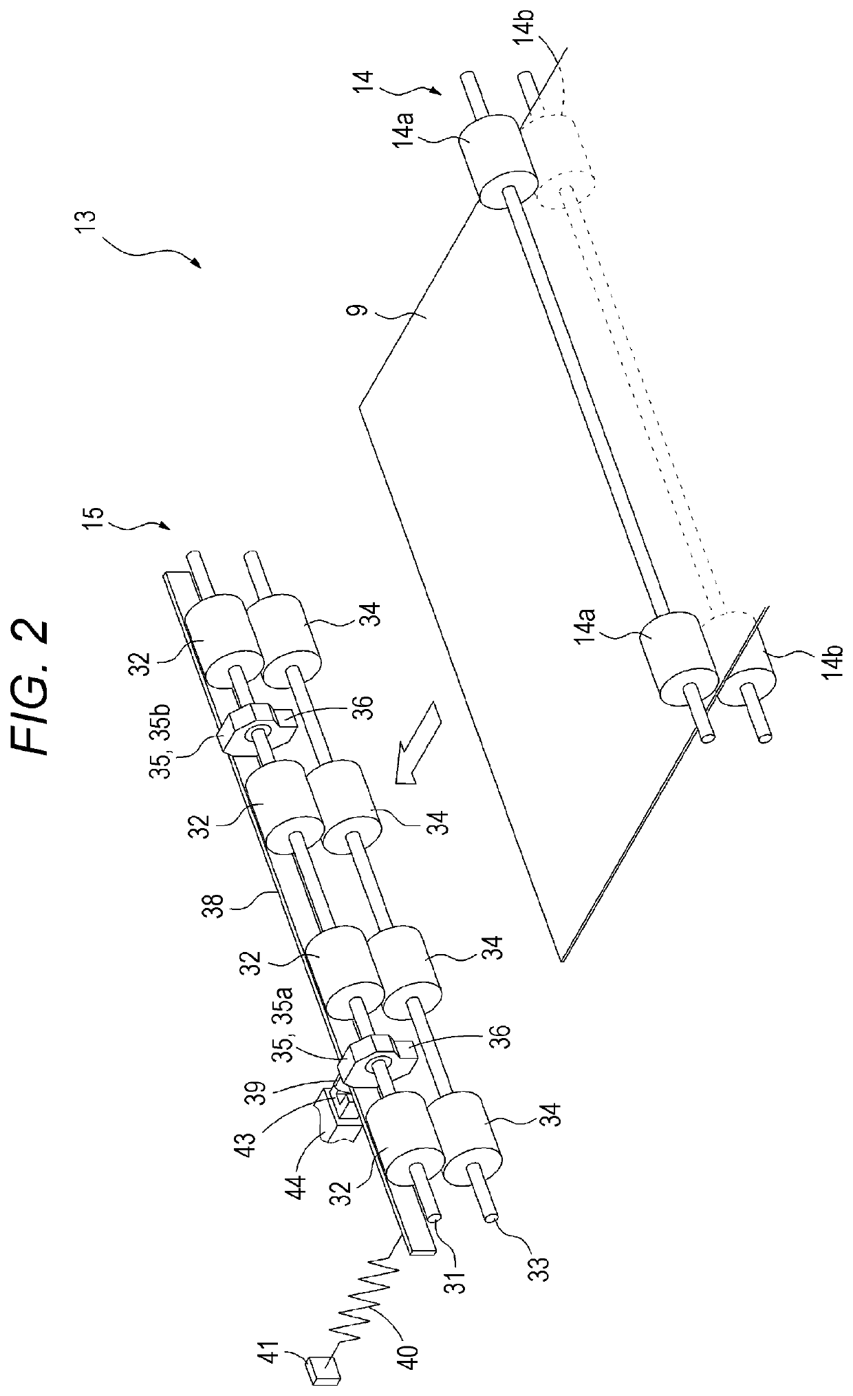
An image forming apparatus includes: a conveyance path that conveys a sheet; registration rollers that are arranged across the conveyance path and each comprise a nip part; a sheet locking member that locks a front end of a sheet conveyed in the conveyance path, where the sheet locking member swings between a first attitude and a second attitude, in the first attitude the sheet locking member locks the sheet on an upstream side of the nip part, and in the second attitude the sheet locking member is retracted to a downstream side of the nip part and allows the sheet to pass through the nip part; an energizer that energizes the sheet locking member to maintain the first attitude; and a hardware processor that detects deterioration of the energizer.

Description

CROSS-REFERENCE TO RELATED APPLICATION[0001]The entire disclosure of Japanese patent Application No. 2018-240906, filed on Dec. 25, 2018, is incorporated herein by reference.BACKGROUNDTechnical Field[0002]The present invention relates to an image forming apparatus, an image forming system, and a deterioration detection method, and more particularly to technology for detecting deterioration of a mechanism that performs sheet skew correction.Description of the Related Art[0003]In the related art, a mechanism in which gate members (shutter members) that contact the front end of a sheet upstream of a nip part of a pair of registration rollers and lock the front end of the sheet is known as a mechanism for correcting the skew of a sheet in an image forming apparatus (for example, JP 2011-190026 A). The gate members include a plurality of sheet locking parts arranged along a direction perpendicular to the sheet conveyance direction, and performs skew correction of the sheet by causing the...

Claims


Application Information

Patent Timeline
Patent Type & Authority Applications(United States)
IPC IPC(8): G03G15/00B65H9/00B65H5/06
CPCB65H9/004B65H2511/242G03G15/6564B65H5/062G03G15/6567G03G15/55B65H2402/54B65H2601/121B65H2601/324B65H2601/423B65H2511/417B65H7/02B65H2513/50B65H2515/84B65H2220/01B65H2511/24
Inventor KIMURA, TAKUKAMIYA, MASAHIROMASUDA, JUNICHINONOYAMA, MASAHIROCHO, KOUEIISHIKAWA, AKIMASA
Owner KONICA MINOLTA INC
Learn More