
Aspirators for evacuation assemblies

a technology of inflating air and aspirator, which is applied in the direction of aircraft ejection means, jet pumps, non-positive displacement pumps, etc., can solve the problems of limiting the size of the compressed gas source required to inflate the evacuation assembly, and reducing the efficiency of the aspirator, so as to limit the resistance to a primary

Active Publication Date: 2020-06-18
THE BF GOODRICH CO
View PDF0 Cites 0 Cited by
  • Summary
  • Abstract
  • Description
  • Claims
  • Application Information

AI Technical Summary

Benefits of technology

The patent text describes an aspirator for an evacuation assembly that has low resistance to the primary gas flow, which means that a smaller compressed gas source is needed for the same inflation requirements. This is achieved by designing the aspirator with a duct, a vane, and a nozzle that work together to limit the resistance to the gas flow.

Problems solved by technology

Such inflatable evacuation assemblies are typically inflated using a compressed gas source, generally in cooperation with an aspirator, which limits the size of the compressed gas source required to inflate the evacuation assembly.
The efficiency of the aspirator typically corresponds to the arrangement of the nozzles within the duct, turns in the conduit connecting the compressed supply typically reducing the efficiency of the aspirator and requiring larger volumes of compressed gas for a given inflation requirement.

Method used


Image

  • Aspirators for evacuation assemblies
  • Aspirators for evacuation assemblies
  • Aspirators for evacuation assemblies

Examples


Embodiment Construction

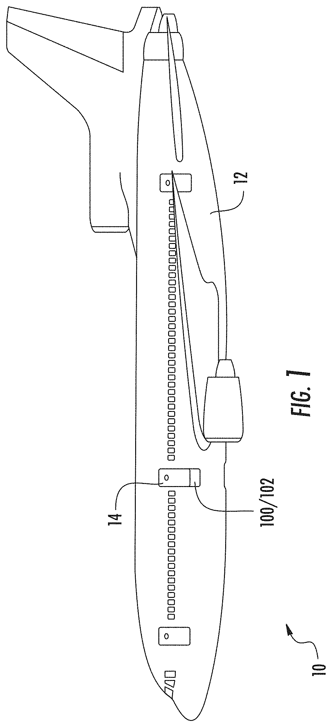
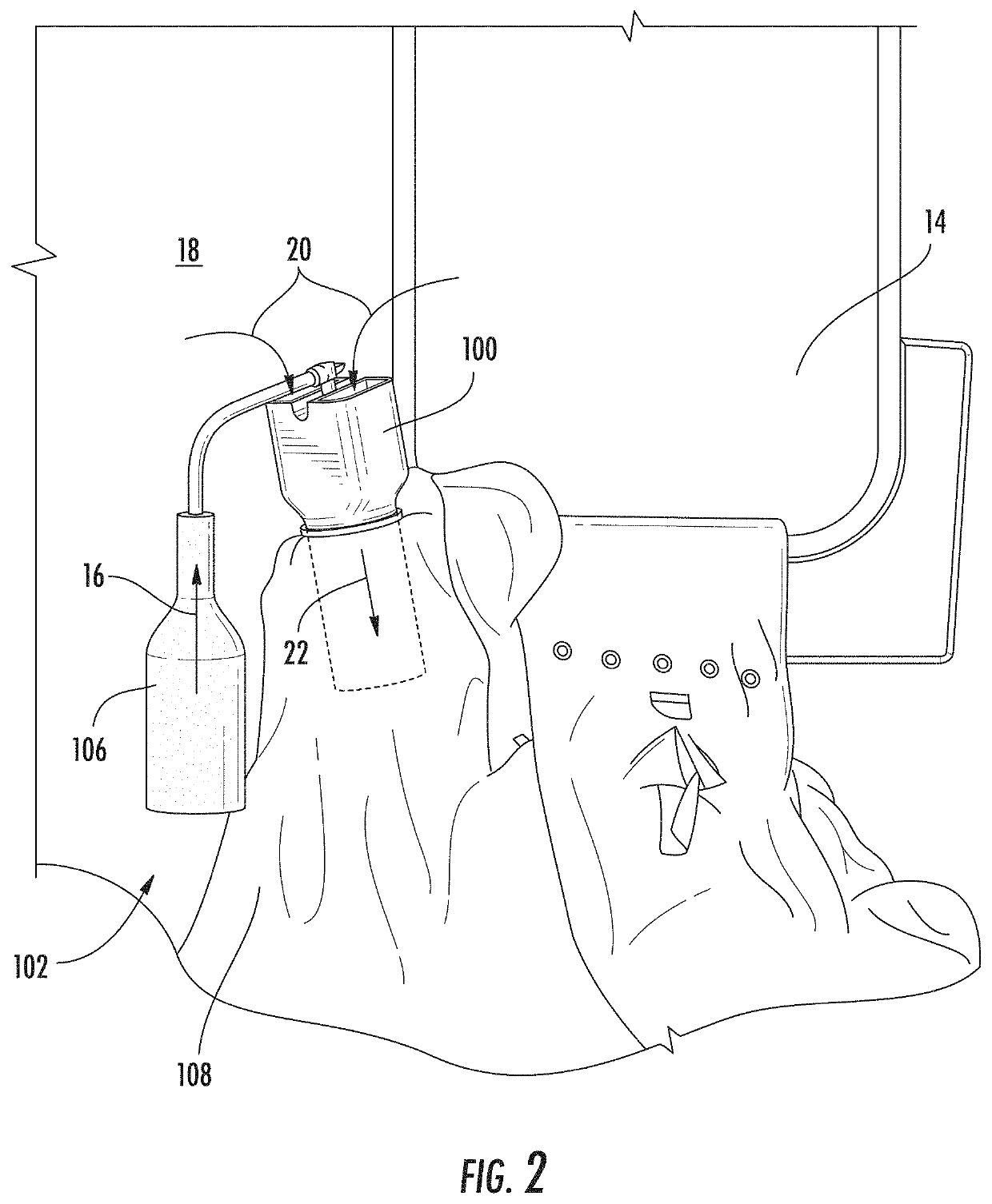
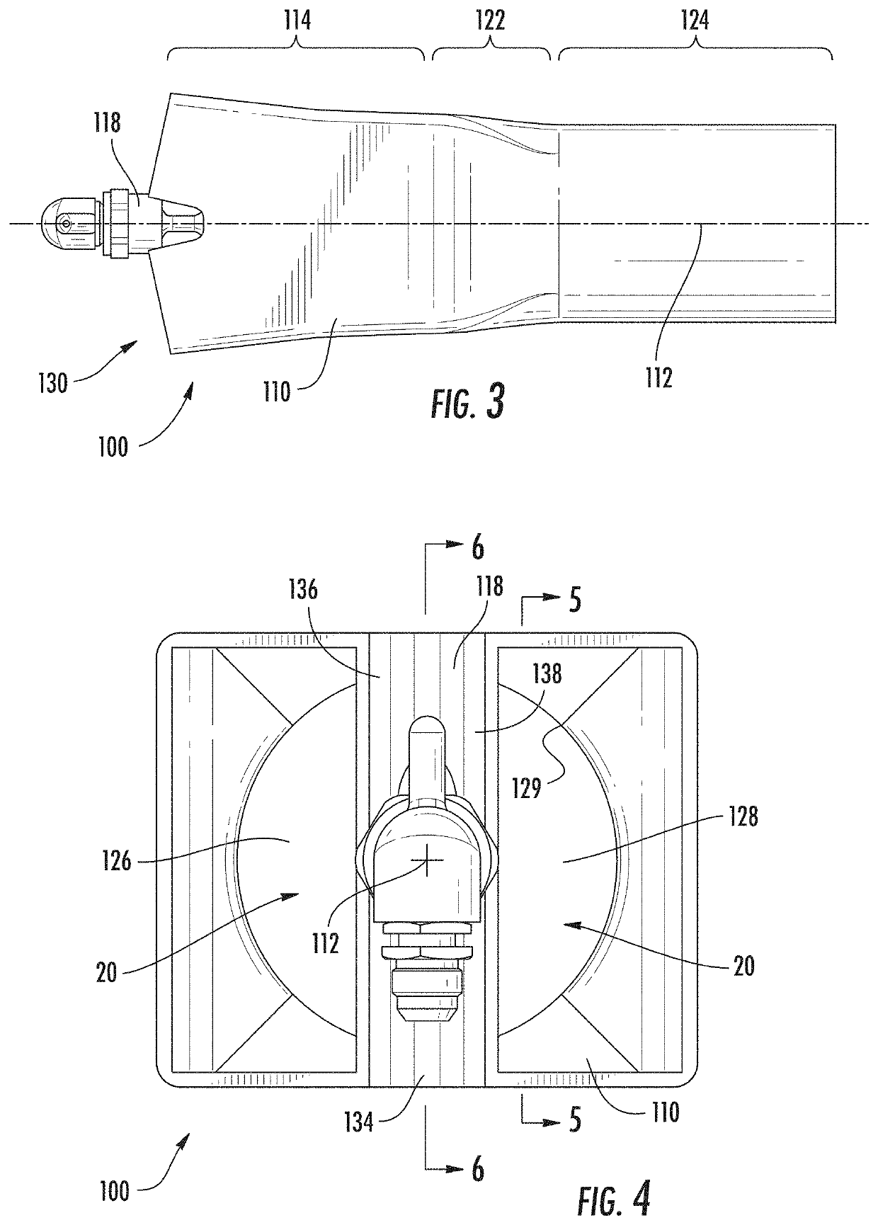
[0037]Reference will now be made to the drawings wherein like reference numerals identify similar structural features or aspects of the subject disclosure. For purposes of explanation and illustration, and not limitation, a partial view of an exemplary embodiment of an aspirator in accordance with the disclosure is shown in FIG. 1 and is designated generally by reference character 100. Other embodiments of aspirators and evacuation assemblies employing aspirators in accordance with the present disclosure, or aspects thereof, are provided in FIGS. 2-9, as will be described. The aspirators and evacuation assemblies described herein can be used for inflating evacuation devices like slides, pontoons, and / or life rafts on vehicles, such as in marine and aerospace applications, though the present disclosure is not limited to a particular application or to any particular type of inflatable body in general.

[0038]Referring to FIG. 1, an aircraft 10 is shown. Aircraft 10 includes a fuselage 1...


PUM


Abstract

An aspirator for an evacuation assembly includes a duct defining a flow axis with an upstream portion and a downstream portion, a vane spanning the upstream portion of the duct, and a nozzle. The nozzle has an outlet, is supported by the vane, and is positioned within the upstream portion of the duct. The outlet is laterally offset from the flow axis and is axially overlapped by the vane to limit resistance to a primary gas flow entering the duct through the outlet of the nozzle. Evacuation assemblies are also described.

Description

CROSS REFERENCE TO RELATED APPLICATIONS[0001]This application claims the benefit of Indian Application No. 201811047703, filed Dec. 17, 2018, the contents of which is incorporated herein by reference in its entirety.BACKGROUND[0002]The present disclosure relates to vehicle evacuation assemblies, and more particularly to aspirators for inflating evacuation devices such as on aircraft.[0003]Vehicles, such as ships and aircraft, commonly carry evacuation assemblies for the safe disembarkation of passengers and crew. In the case of aircraft, for example, inflatable evacuation slides may be deployed to provide an exit for crew and passengers from aircraft if a jetway or other means of egress for passengers are not available. In the case of ships and some aircraft, rafts or pontoons may be deployed to provide a means of flotation for egressing passengers and crew or to provide flotation of the aircraft itself in the event of a water landing. Such inflatable evacuation assemblies are typic...

Claims


Application Information

Patent Timeline
Patent Type & Authority Applications(United States)
IPC IPC(8): F04F5/46B64D25/14
CPCB64D25/14F04F5/466F04F5/16F04F5/46F04F5/463
Inventor KUPPAN, SKANDAN BERIKAI
Owner THE BF GOODRICH CO
Learn More