
Systems and methods for increasing power output in a waste heat driven air brayton cycle turbocharger system

a technology of waste heat and turbocharger, which is applied in the direction of special engines, machines/engines, mechanical equipment, etc., can solve the problems of reducing the efficiency limiting the power output of the rotary machine in such ambient conditions, and limiting the power output of the rotary machin

Active Publication Date: 2020-06-18
GE GLOBAL SOURCING LLC
View PDF0 Cites 3 Cited by
  • Summary
  • Abstract
  • Description
  • Claims
  • Application Information

AI Technical Summary

Benefits of technology

This patent describes a power generation system that includes a rotary machine, a heat exchanger, and a turbocharger system. The system has two turbochargers, a low pressure turbine and a high pressure turbine, which work together to compress air and feed it to the rotary machine. The system also includes an auxiliary combustor that injects heated exhaust gases into the turbines to improve their performance. The technical effects of this system include improved air compression and higher efficiency of power generation.

Problems solved by technology

A power output of such rotary machines is limited by a mass flow rate of working fluid (e.g., air) through the rotary machine.
For example, a compressor intake mass flow of the rotary machine is decreased during high temperature ambient conditions due to a decrease in ambient air density, limiting the power output of the rotary machine in such ambient conditions.
However, as a quantity of air extracted from the compressor for cooling or other purposes increases, an efficiency of the rotary machine decreases.
As another example, a temperature of the air through the rotary machine may limit the power output of the rotary machine due to the need to maintain a temperature at the inlet of the turbine within temperature thresholds that are dependent on the materials of the turbine.

Method used


Image

  • Systems and methods for increasing power output in a waste heat driven air brayton cycle turbocharger system
  • Systems and methods for increasing power output in a waste heat driven air brayton cycle turbocharger system
  • Systems and methods for increasing power output in a waste heat driven air brayton cycle turbocharger system

Examples


Embodiment Construction

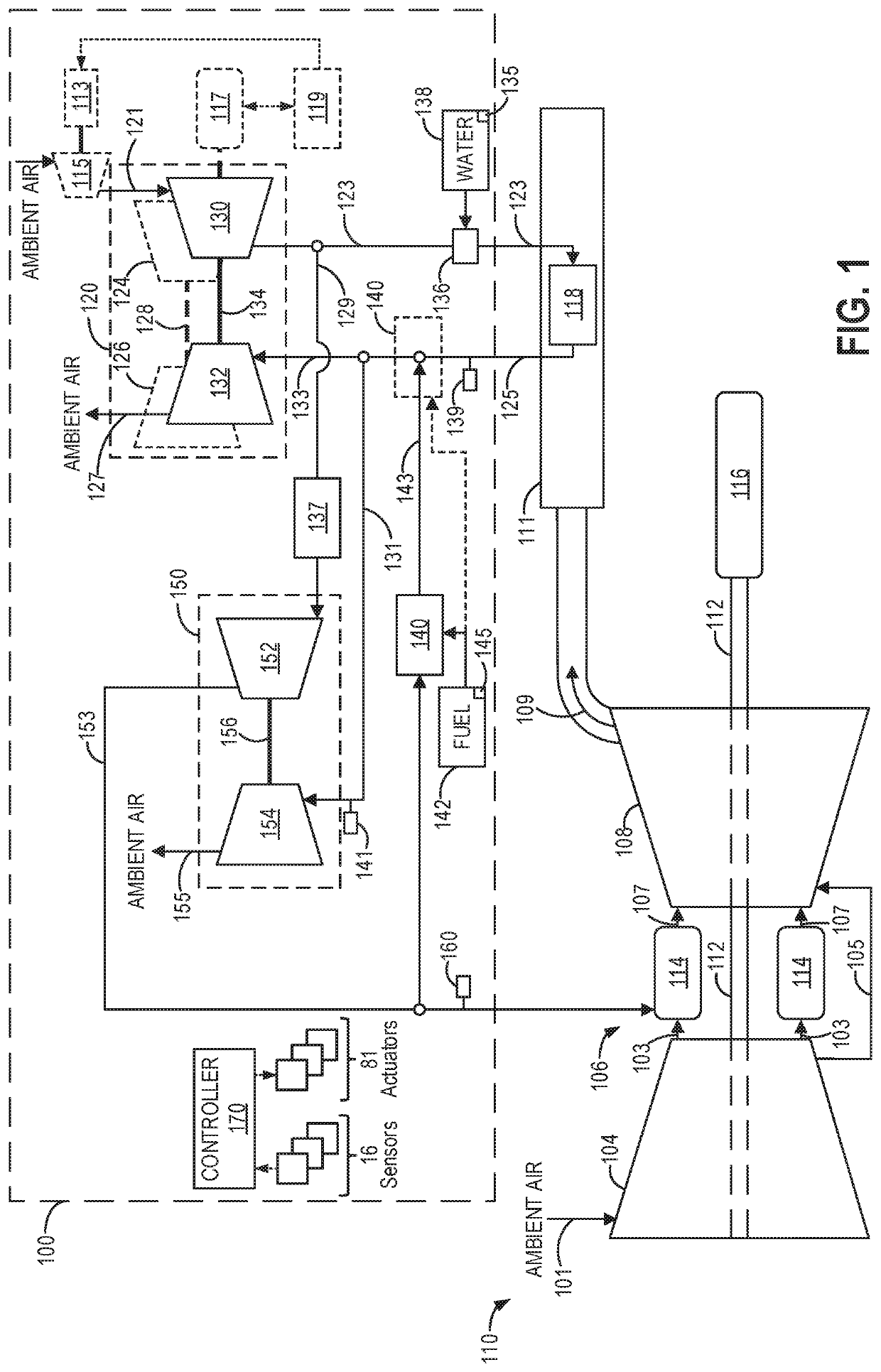
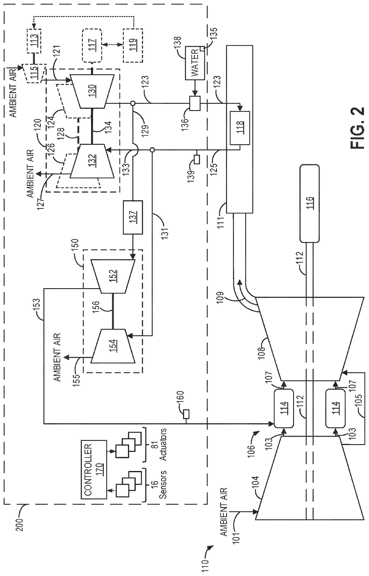
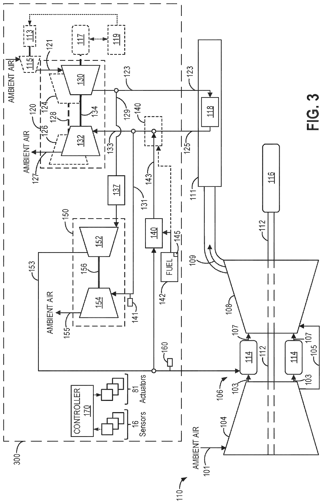
[0013]The following description relates to embodiments of a system for use with a power generator having a rotary machine including a first combustor and an exhaust passage flowing exhaust gases from the first combustor, including: a heat exchanger positioned in the exhaust passage; and a turbocharger system, comprising: at least one low pressure turbocharger including a low pressure turbine fluidly coupled to an outlet of the heat exchanger, the low pressure turbine adapted to receive gas flow from the heat exchanger, and a low pressure compressor fluidly coupled to an inlet of the heat exchanger, the low pressure compressor adapted to supply compressed air to the heat exchanger; at least one high pressure turbocharger including a high pressure turbine fluidly coupled to the outlet of the heat exchanger, the high pressure turbine adapted to receive gas flow from the heat exchanger, and a high pressure compressor fluidly coupled to the rotary machine, the high pressure compressor ad...


PUM


Abstract

Various systems and methods are provided for a turbocharger system. In one example, system for use with a power generator having a rotary machine including a combustor comprises: a heat exchanger positioned to receive exhaust gases from the combustor; and a turbocharger system, comprising: a low pressure turbocharger including a low pressure turbine adapted to receive gas flow from the heat exchanger and a low pressure compressor adapted to supply compressed air to the heat exchanger; a high pressure turbocharger including a high pressure turbine adapted to receive gas flow from the heat exchanger and a high pressure compressor adapted to receive gas flow from the low pressure compressor and supply compressed air to the rotary machine; and a second combustor adapted to inject exhaust gases into a flow path arranged between the heat exchanger and an inlet to each of the high pressure turbine and the low pressure turbine.

Description

BACKGROUNDTechnical Field[0001]Embodiments of the subject matter disclosed herein relate to turbocharger systems for use with a rotary machine.Discussion of Art[0002]Some rotary machines, such as some gas turbine engines, include a compressor, a combustor, and a turbine coupled in a serial flow relationship. More specifically, the compressor receives ambient air (e.g., via an intake) and discharges compressed air. The compressed air is then mixed with fuel and ignited in the combustor to produce a high energy gas stream. The high energy gas stream flows through the turbine to rotatably drive the turbine. The compressor and turbine are coupled through a shaft to form a rotor assembly, such that rotation of the turbine drives the compressor and a load coupled to the shaft.[0003]A power output of such rotary machines is limited by a mass flow rate of working fluid (e.g., air) through the rotary machine. For example, a compressor intake mass flow of the rotary machine is decreased durin...

Claims


Application Information

Patent Timeline
IPC IPC(8): F02B37/20F01K23/10F02B37/013F02B37/007F02B37/10F02C6/18F02G5/02
CPCF02B37/007F01K23/101F02G2250/03F02C6/18F02B37/10F02G5/02F02B37/20F02B37/013F02C7/10F02C7/143F02C3/30F02C6/12F05D2220/60F05D2220/40F05D2260/211F05D2260/213Y02E20/16Y02T10/12
Inventor HOMISON, CHRISTOPHER JOSEPHJOHNSON, LUKASLORINGER, DANIEL EDWARD
Owner GE GLOBAL SOURCING LLC
Learn More