
Sintered oil-impregnated bearing

Pending Publication Date: 2020-06-11
DIAMET CORP
View PDF0 Cites 0 Cited by
  • Summary
  • Abstract
  • Description
  • Claims
  • Application Information

AI Technical Summary

Benefits of technology

The present invention is a sintered oil-impregnated bearing that has excellent wear resistance and cost performance under severe use conditions. The bearing material contains copper, carbon, iron, and impurities, with a metal structure containing copper and pearlite or ferrite scattered throughout the matrix. This results in a strong bearing material with good lubricity. The bearing material is particularly useful in high-load and vibration environments such as electric motors and wiper motors in vehicles.

Problems solved by technology

Further, the problem with the conventional bearings used in these motors is that in addition to the fact that a bearing often collides with a shaft due to vehicle vibration, the use condition has now become more severe than before, which has led to an insufficient wear resistance.
However, these materials are such that depending on a sintering condition(s), a large amount of a hard cementite may be precipitated by the reaction between iron and graphite so that wear may progress as a mating shaft member will be damaged thereby; and are such that even with the precipitation of a hard cementite being suppressed by performing sintering at a low temperature at which iron and graphite are less likely to react with each other, the strength of a bearing may be insufficient so that the bearing will be worn due to a collision incurred by a high load and vibration.
However, the iron-based sliding member disclosed in Patent document 1 has a high percentage of iron in its material; upon collision due to a high load and vibration, since a mating shaft member is also a steel member, adhesion which is likely to occur between same type of metal shall make it difficult to restrict the wear of the bearing and the shaft.
Moreover, in the case of the iron-based sintered bearing disclosed in Patent document 2, a sintering temperature employed is low such that an insufficient material strength is exhibited, thus making it difficult to deal with the collision incurred by a high load and vibration.

Method used


Image

  • Sintered oil-impregnated bearing
  • Sintered oil-impregnated bearing
  • Sintered oil-impregnated bearing

Examples


working example

[0043]As a raw material powder(s), there were prepared a reduced iron powder for powder metallurgy, an electrolytic copper powder and a graphite powder. Particularly, as a copper powder, an electrolytic copper powder having a given average particle size was used, except that in comparative example 5, an atomized copper powder having a small average particle size was used; and that in comparative example 6, an electrolytic copper powder having a large average particle size was used. As a graphite powder, a crystalline graphite powder or flake graphite powder having a given average particle size was used, except that in comparative example 7, an artificial graphite powder having a small average particle size was used; and that in comparative example 8, a crystalline graphite powder or flake graphite powder having a large average particle size was used.

[0044]These raw material powders were mixed together so that a final component composition(s) shown in Table 1 could be achieved. A zin...


PUM

PropertyMeasurementUnit
Percent by massaaaaaaaaaa

Abstract

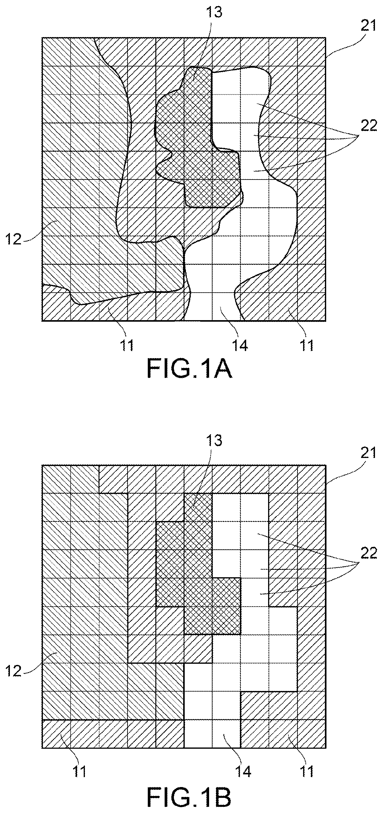
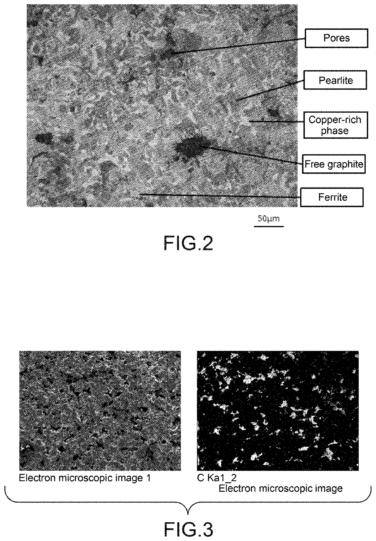
Provided is a novel sintered oil-impregnated bearing superior in wear resistance and cost performance under a severe use condition where the bearing collides with a shaft due to a high load and vibration, such as a condition associated with an output shaft of an electric motor installed in a vehicle and a wiper motor installed therein. The sintered oil-impregnated bearing contains: 15 to 30% by mass of Cu; 1 to 4% by mass of C; and a remainder consisting of Fe and inevitable impurities, in which a metal structure with copper being melted therein is provided at least on a bearing surface; pearlite or a pearlite with ferrite being partially scattered therein is provided in a matrix; a copper-rich phase arranged in a mesh-like manner is also provided in the matrix; and a free graphite is dispersed and distributed in the matrix as well.

Description

CROSS-REFERENCE TO RELATED PATENT APPLICATIONS[0001]This application is a U.S. National Phase Application under 35 U.S.C. § 371 of International Patent Application No. PCT / JP2018 / 034712, filed Sep. 20, 2018, and claims the benefit of priority to Japanese Patent Application No. 2017-180541, filed Sep. 20, 2017, all of which are incorporated by reference herein in their entireties. The International Application was published in Japanese on Mar. 28, 2019 as International Publication No. WO / 2019 / 059248 under PCT Article 21(2).FIELD OF THE INVENTION[0002]The present invention relates to a sintered oil-impregnated bearing used under a high-load use condition such as that associated with a motor in a vehicle or the like, the sintered oil-impregnated bearing having a superior wear resistance and a lower attackability against other members.BACKGROUND OF THE INVENTION[0003]Sintered oil-impregnated bearings are employed even under a condition(s) involving a relatively high load, such as a cond...

Claims


Application Information

Patent Timeline
IPC IPC(8): B22F5/00C22C1/04C22C38/16C22C33/02B22F1/052
CPCB22F5/00C22C38/16C22C38/008C22C1/0475B22F2005/004C22C33/0278B22F3/1035B22F3/11B22F5/106F16C33/104F16C33/128F16C2204/12F16C2204/14F16C2202/10F16C2202/52C22C1/10C22C1/08B22F2999/00B22F1/052C22C2200/00
Inventor ISHII, YOSHINARIMARUYAMA, TSUNEO
Owner DIAMET CORP
Learn More