Skin treatment apparatus utilising intense pulsed light (IPL)
a skin treatment and pulsed light technology, applied in the field of skin treatment apparatus, can solve the problems of reducing the capacitor voltage to reflect the required output for the current sensor measurement, further delays, and difficulty for users in knowing when the apparatus was working correctly, so as to improve the accuracy of actual energy output and achieve self-correction
- Summary
- Abstract
- Description
- Claims
- Application Information
AI Technical Summary
Benefits of technology
Problems solved by technology
Method used
Image
Examples
embodiment 1
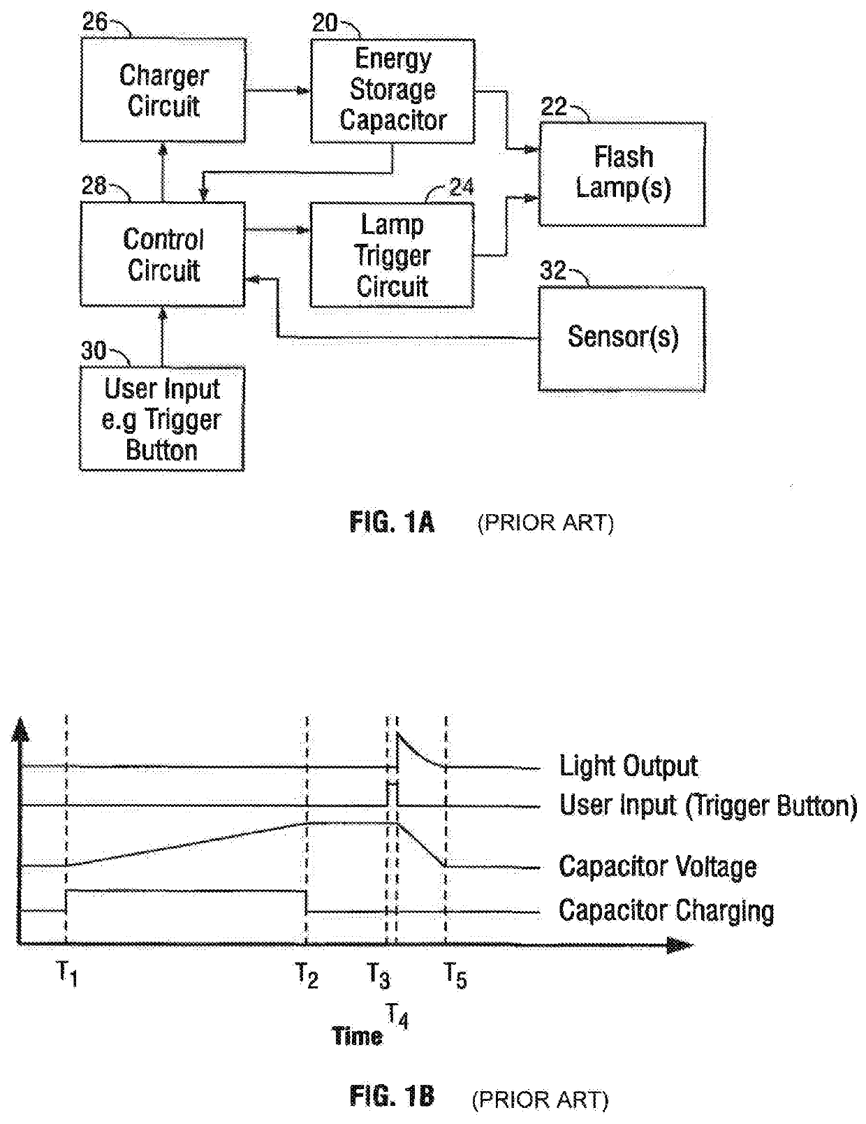
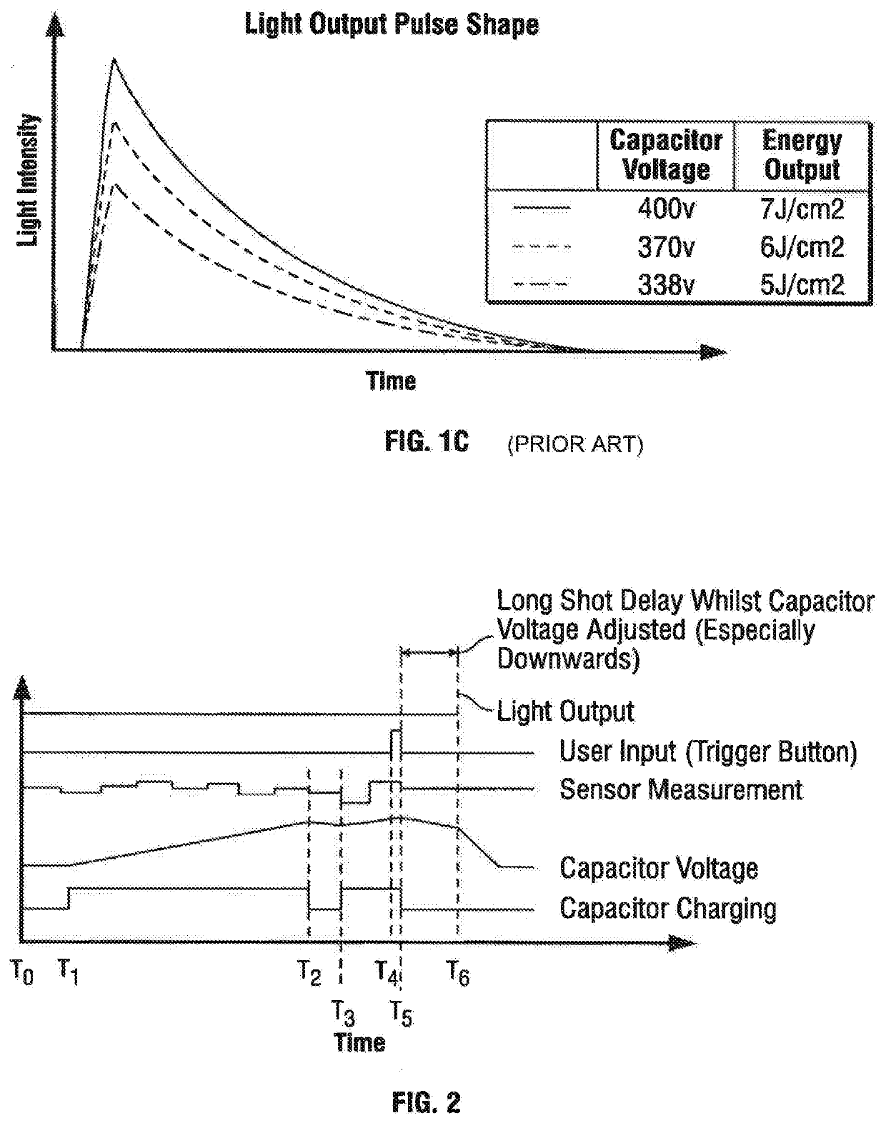
[0097]Reference is now made to FIGS. 4A to 4C. FIG. 4A shows in block diagram form components utilising a first embodiment of the present invention. The diagram is similar to the diagram of FIG. 1A, and like components have been identified with the same reference numerals. It should be noted, however, that in this embodiment there is the additional component of a discharge control element (80) such as an electronic switch (e.g. Mosfet) which may be provided in a flash pulse termination circuit as identified in the block diagram which is arranged to terminate discharge energy from the energy storage device (20) to the flashlamp (22). The effect of the provision of a discharge control element (80) in the flash pulse termination circuit (80) is that the light output pulse shape as shown in FIG. 4C can be terminated in order that a desired energy output is achieved. It will be appreciated that this is irrespective of the initial voltage of the energy storage device. In FIG. 4C the volta...
embodiment 2
[0100]In a second embodiment of the present invention, the energy storage device may include a plurality of individual storage device elements such as individual capacitors. The control circuit (28) is arranged to control discharge of the plurality of individual charge storage elements, and may independently control discharge of each of the individual charge storage elements. Release from the charge storage elements may be enabled by the control system sequentially or simultaneously. This may be achieved through the provision of an energy storage device switching circuit (82) which may be termed a capacitor switching circuit. The energy output as identified in FIG. 5C can be manipulated as required dependent on the sensor input to the control circuit (28) without the requirement to charge the multiple energy storage capacitors as a result of the input from the sensor (32). The multiple energy storage capacitors may be charged to, for example, 400 volts as represented in FIG. 5C. The...
embodiment 3
[0102]Referring now to FIGS. 6A to 6C, a third exemplary embodiment of the present invention is presented and again, like components have been presented with the same reference numerals. In one embodiment of the present invention in order to minimise the time delay between user input and their desire to activate the apparatus and the actual light output, the energy storage device (20) can be charged to an intermediate value. This may be independently of the input of the sensor (32). Charging is carried out to a predetermined intermediate voltage and this voltage can effectively be topped up dependent on the skin tone determined by the sensor at the time the user activates the input. As such in this embodiment the energy storage device (20) may be charged independently of the sensor input to a voltage of, for example, 300 volts and this voltage can be boosted dependent on the skin tone measurements. At T0 as represented in FIG. 6B, the device is switched on and at T1 a user input cau...
PUM
| Property | Measurement | Unit |
|---|---|---|
| voltage | aaaaa | aaaaa |
| voltage | aaaaa | aaaaa |
| capacitor voltage | aaaaa | aaaaa |
Abstract
Description
Claims
Application Information
 - R&D
- Intellectual Property
- Life Sciences
- Materials
- Tech Scout
- Unparalleled Data Quality
- Higher Quality Content
- 60% Fewer Hallucinations
Browse by: Latest US Patents, China's latest patents, Technical Efficacy Thesaurus, Application Domain, Technology Topic, Popular Technical Reports.
© 2025 PatSnap. All rights reserved.Legal|Privacy policy|Modern Slavery Act Transparency Statement|Sitemap|About US| Contact US: help@patsnap.com


