
Weighing method and storage medium thereof

a weighing method and storage medium technology, applied in the field of weighing methods, can solve the problems of weighing errors, long time for operations, and requiring additional human operations, and achieve the effect of improving work efficiency

Active Publication Date: 2020-06-04
METTLER TOLEDO CHANGZHOU PRECISION INSTR +2
View PDF0 Cites 2 Cited by
  • Summary
  • Abstract
  • Description
  • Claims
  • Application Information

AI Technical Summary

Benefits of technology

The present invention provides a system and method for accurately weighing objects in both horizontal and inclined states. It calculates errors caused by the weighing scale platform and the placement position of the measured object, and uses these errors to correct the weighing results. This method is simple and efficient, and does not require human participation. It is also compatible with the calculation of errors caused by the weighing position under the inclined state and the horizontal state, making it easy to apply and having a wide range. Overall, the present invention improves weighing accuracy and efficiency.

Problems solved by technology

Therefore, this requires additional human operations and the time for the operations is long.
When performing weighing, it is generally necessary to place the centre of gravity of the weighed product in the centre of the weighing scale platform, while during the actual application, the centre of gravity of the weighed product is not in the centre of the weighing scale platform due to the difference in the placement position and the uneven density of the weighing product, which also leads to weighing errors, called eccentric load error.
The disadvantages of this method are as follows: first, this method requires human manual operation, so that the efficiency is low, and due to the different measuring positions of placing the weights and the effects of the number of the measuring positions on the calculation of the adjustment parameters, the final weighing value is affected; second, when a final user uses the electronic weighing scale, if the table on which the electronic weighing scale is placed is inclined, while the final user does not adjust the eccentric load error, but directly uses the electronic weighing scale for measurement, the inclined table and the measuring position where the weighing object is placed will affect the weighing value.

Method used


Image

  • Weighing method and storage medium thereof
  • Weighing method and storage medium thereof
  • Weighing method and storage medium thereof

Examples


first embodiment

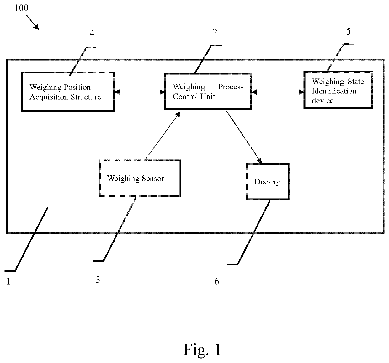
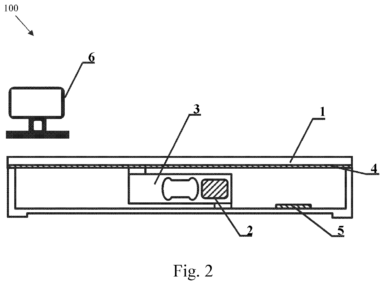
[0036]FIG. 1 shows a block diagram of the electronic weighing structure of the present invention. FIG. 2 shows a schematic diagram of an electronic scale structure to which the block diagram of the electronic weighing structure shown in FIG. 1 is applied.

[0037]As shown in FIGS. 1 to 2, the electronic weighing structure comprises:

[0038]a weighing scale platform 1, wherein a measured object is placed on the weighing scale platform 1 for weighing;

[0039]a weighing sensor 3 located inside a weighing scale body 100, which is used for converting the weight of the measured object into deformation of an elastomer element, and then converting the deformation into an electrical signal for identification and measurement, so as to obtain the weight of the weighed object;

[0040]a weighing process control unit 2 mounted on the weighing sensor 3, which is the core module of the entire weighing system, and is used for acquiring the original weighing signal output by the weighing sensor and performing...

second embodiment

[0058]If the weighing scale platform 1 is large, a plurality of weighing sensors 3 may be mounted, and as shown in FIG. 4, a schematic diagram of another electronic scale structure to which the block diagram of the electronic weighing structure shown in FIG. 1 is applied.

[0059]The differences between the second embodiment and the first embodiment are as follows: in the first embodiment, there is only one weighing sensor 3, and the weighing position acquisition structure 4 acquires the coordinates (x0, z0) of the measured object; while the second embodiment comprises four weighing sensors 3 which are respectively provided at four corners within the weighing scale body 100, and a weighing process control unit 2 is provided on any one of the weighing sensors 3; the weighing state identification device 5 can be independently mounted inside the weighing scale body 100, and can also be integrated in the weighing process control unit 2 of any one of the weighing sensor 3.

[0060]In this embo...

third embodiment

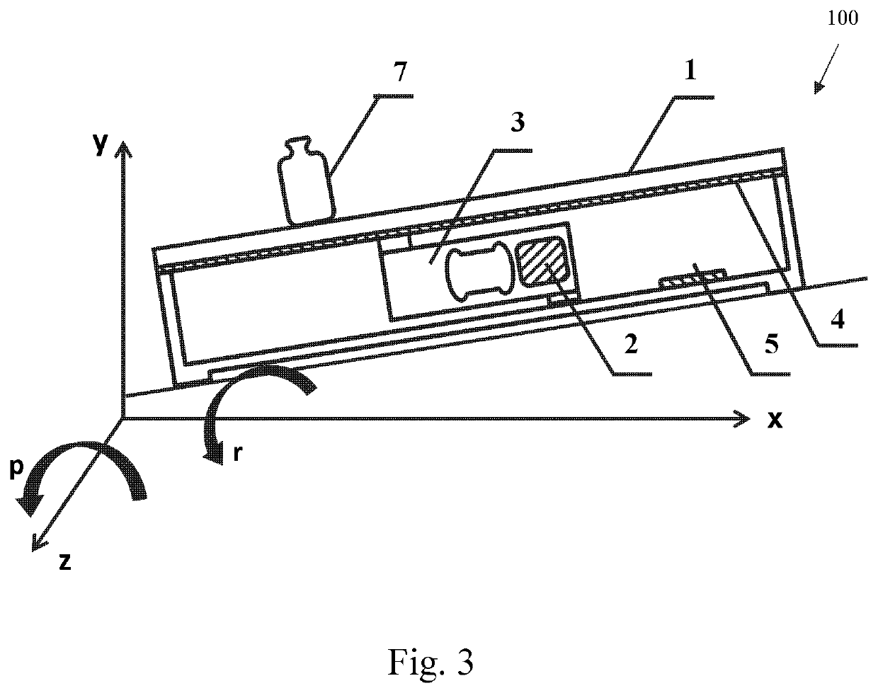
[0072]The differences between the third embodiment and the first embodiment are as follows: in the first embodiment, the weighing scale platform 100 is inclined, so the roll angle r and the pitch angle p are required to be obtained; while in the third embodiment, the weighing scale platform 100 is placed horizontally, so the roll angle r=0, the pitch angle p=0, and the calculation method thereof is as follows:

[0073]Step 31: reading coordinates (x0, z0) of the centre of gravity of a measured object 7, wherein x0 is the coordinate of the centre of gravity of the measured object 7 on the x-axis, and z0 is the coordinate of the centre of gravity of the measured object 7 on the z-axis.

[0074]Step 32: calculating an error2 caused by a weighing position according to the following formula:

error2=f(x0,z0)=(1,x0,z0,x0z0,x0z02,x02z0,x02,z02)*(a11a12a13…a18a21a22a23…a28…a81a82a83…a88)

[0075]wherein a11, a12, . . . , and a88 are weighing position correction parameters.

[0076]Step 33: finally, calcu...


PUM


Abstract

In a weighing method, a weight (W) of a measured object (7) is measured. A roll angle (r) and a pitch angle (p) of a weighing scale platform (100) are read. The coordinates of a placement position (x0, z0) of the measured object are acquired. A first error (error1) caused by a weighing state according to the roll angle and the pitch angle is calculated. A second error (error2) caused by a weighing position according to the coordinates of the placement position, the roll angle (r) and the pitch angle (p) is also calculated. From these, a corrected weight (Wc) is determined.

Description

FIELD OF THE INVENTION[0001]The present invention relates to a weighing method, and mainly to a weighing method for performing accurate weighing in a horizontal state and an inclined state, and a storage medium.THE RELATED ART[0002]A weighing sensor is a basic element for measuring the weight of an object, which converts the weight of a measured object into the deformation of an elastomer element, and then into an electrical signal for identification and measurement, so as to obtain the weight of the weighed object.[0003]At present, for many commercial scales, especially in high-precision applications, each product will be equipped with a horizontal bubble for adjusting the horizontal state of the weighing scale body, thereby ensuring the metering performance. When using such a product, the position of a horizontal bubble is observed first, and if the horizontal bubble deviates from a horizontal state, adjust four corners of the product, so that the product returns to a horizontal p...

Claims


Application Information

Patent Timeline
Patent Type & Authority Applications(United States)
IPC IPC(8): G01G23/00
CPCG01G23/002G01G23/00
Inventor WU, JIANWEILIN, HONGZHIZHANG, YINGXIE, GUOJUNQIAN, ZHENG
Owner METTLER TOLEDO CHANGZHOU PRECISION INSTR
Learn More