
Controller for HVAC unit

a hvac unit and controller technology, applied in space heating and ventilation control systems, lighting and heating apparatus, heating types, etc., can solve the problems of inability to meet the needs of domestic hvac units, inability to monitor, and expensive sensors and meters

Inactive Publication Date: 2020-05-28
LIRICCO TECH
View PDF0 Cites 18 Cited by
  • Summary
  • Abstract
  • Description
  • Claims
  • Application Information

AI Technical Summary

Benefits of technology

The invention is a method that calculates the minimum power cost over a certain period of time using input power and power cost rates. This allows for the most efficient use of power and reduces the overall cost of adjustment.

Problems solved by technology

Such controllers, however, only take into account environmental variables such as room temperature and humidity when controlling an HVAC unit.
A major disadvantage of such monitors is that specialist sensors and meters are required throughout the system.
Such sensors and meters are costly and not feasible for domestic HVAC units.

Method used


Image

  • Controller for HVAC unit
  • Controller for HVAC unit
  • Controller for HVAC unit

Examples


example 1

[0066]As a specific example, assume that the HVAC unit has, as an efficiency measure, a kW / ton rating of 1.33 at an input power of 40 kW, thereby providing a nominal heat transfer in the form of 30 tons of refrigeration capacity. However, the HVAC unit has a kW / ton rating of 1.50 at an input power of 60 kW, thereby providing a nominal heat transfer in the form of 40 tons of refrigeration capacity. Therefore, the HVAC unit has a higher efficiency at 40 kW input power than at 60 kW input power. In this way, the HVAC unit will have an efficiency profile over a range of input powers. Assume 1.33 is the peak efficiency, with the efficiency decreasing on either side of 40 kW of input power, and a target heat transfer of 30 tons delivered over the desired adjustment time achieves the desired indoor temperature by the end of the desired adjustment time. Then to achieve a maximum efficiency measure over the desired adjustment time, the input power profile supplied to the HVAC unit would comp...

example 2

[0067]However, now assume a target heat transfer of 40 tons delivered over the desired adjustment time is required to achieve the desired indoor temperature by the end of the desired adjustment time, and the efficiency of the HVAC unit continues to decrease at input powers above 60 kW. Then to achieve a maximum efficiency measure over the desired adjustment time, the input power profile supplied to the HVAC unit would comprise supplying an input power of 60 kW over the whole desired adjustment time.

example 3

[0068]Now assume that the HVAC unit has a kW / ton rating of 1.20 at an input power of 60 kW, thereby providing a nominal heat transfer in the form of 50 tons of refrigeration capacity, and a kW / ton rating of 1.33 at an input power of 40 kW, thereby providing a nominal heat transfer in the form of 30 tons of refrigeration capacity. Also, assume 1.20 is the peak efficiency, with the efficiency decreasing on either side of 60 kW of input power. Finally, assume a target heat transfer of 30 tons delivered over the desired adjustment time achieves the desired indoor temperature by the end of the desired adjustment time. Then to achieve a maximum efficiency measure over the desired adjustment time, the input power profile supplied to the HVAC unit would comprise supplying an input power of 60 kW over the final 60% of the desired adjustment time, that is, 60% of 50 tons, in order to provide the required 30 tons.

[0069]Alternatively or additionally, the input power profile can correspond to a ...


PUM


Abstract

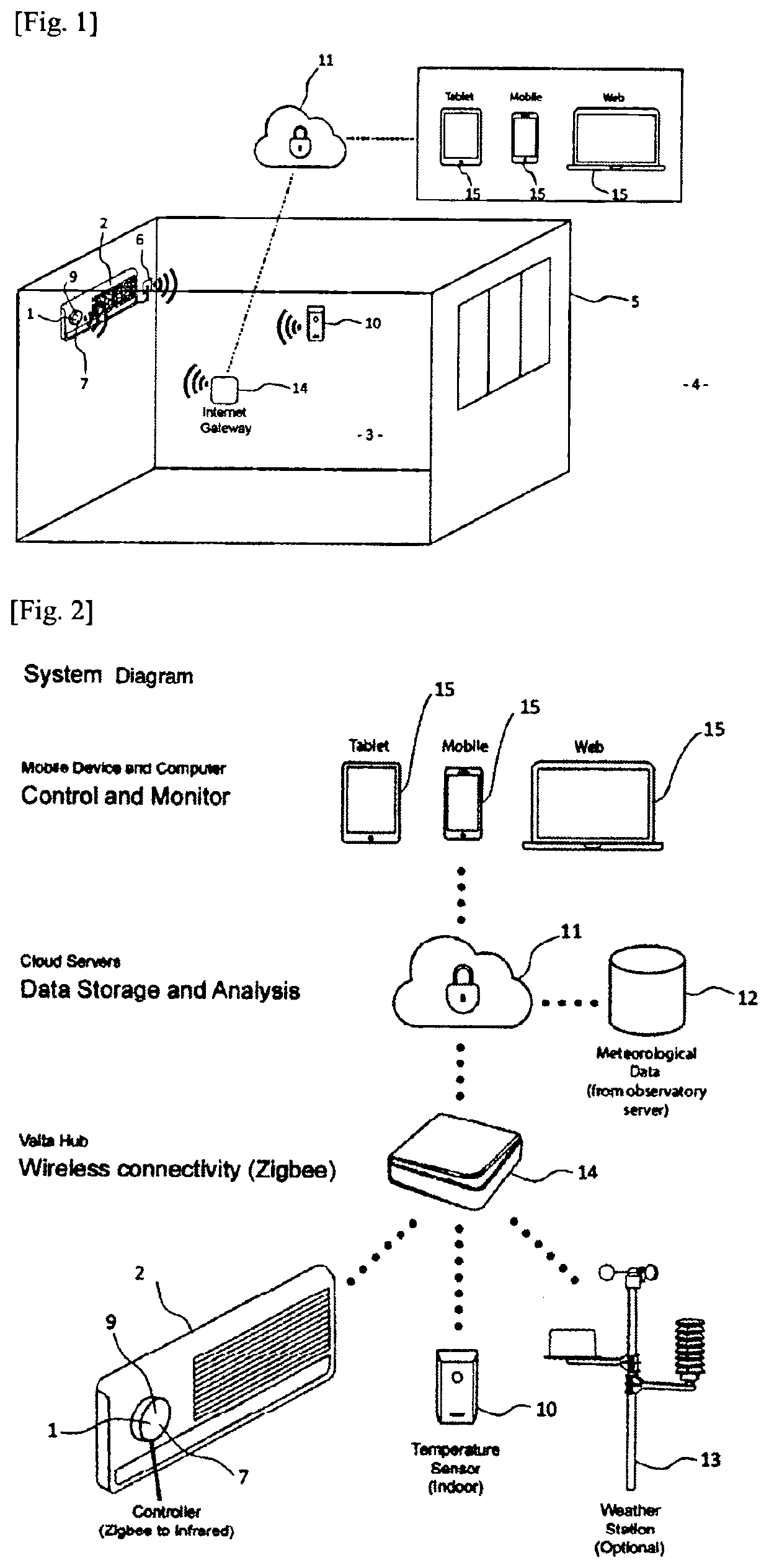
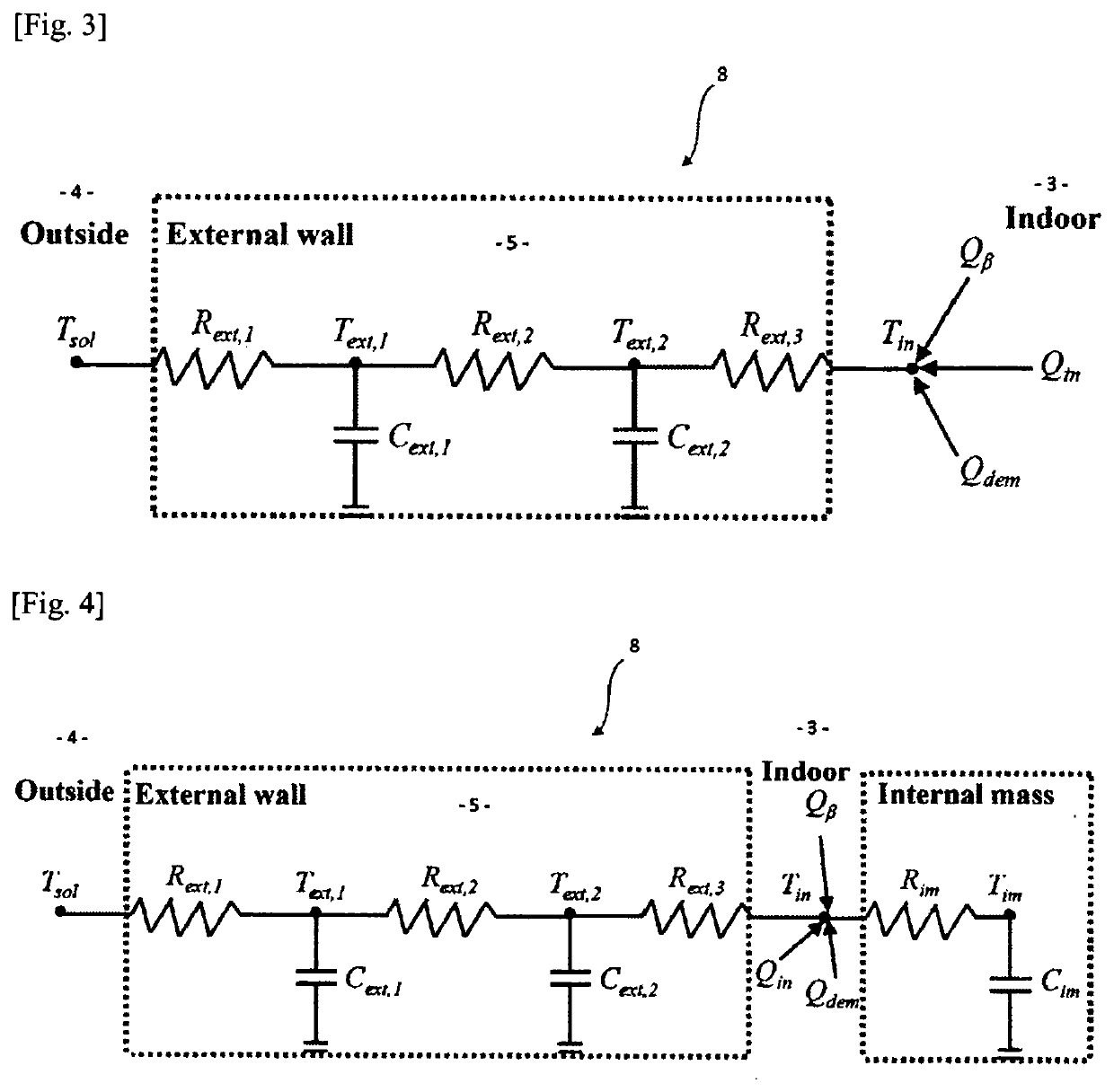
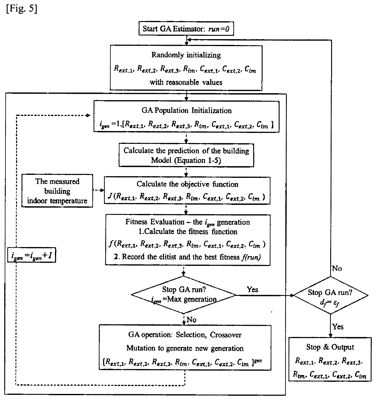
A controller (1) for an HVAC unit (2) for an indoor space (3) separated from an outdoor space (4) by a building envelope (5). The controller (1) comprises a power measurement device (6) for measuring an input power being delivered to the HVAC unit (2). The input power corresponds to a nominal heat transfer provided by the HVAC unit (2). An estimation module (7) calculates a target heat transfer between the HVAC unit (2) and the indoor space (3). The target heat transfer is calculated based on a heat transfer load comprising an external heat transfer between the indoor space (3) and outdoor space(4) calculated in accordance with an ambient indoor temperature of the indoor space (3), an ambient outdoor temperature of the outdoor space (4), and a thermal model (8) of the building envelope (5). A control unit (9) monitors or controls the HVAC unit (2) based on one or both of the input power and the target heat transfer.

Description

TECHNICAL FIELD[0001]The invention relates to controllers and monitors for HVAC units, such as air-conditioners and heat pumps.BACKGROUND ART[0002]Prior controllers for HVAC (heating, ventilation, or air-conditioning) units allow a user to manually adjust settings on an HVAC unit. For example, in the case of an air conditioner, a user typically adjusts a temperature setting and / or a fan speed setting, usually by way of an infrared remote control.[0003]More sophisticated prior controllers automatically adjust settings on an HVAC unit based on a programmed schedule or on feedback from room sensors such as temperature or humidity sensors. For example, where an air conditioner is used to cool a room, if the room temperature rises to a selected set point, the prior controller will increase the fan speed until the temperature sensor detects that the room temperature has fallen back below the set point. The prior controller will then decrease the fan speed. The prior controller cycles thro...

Claims


Application Information

Patent Timeline
Patent Type & Authority Applications(United States)
IPC IPC(8): F24F11/30F24F11/62F24F11/56
CPCF24F2110/12F24F11/56F24F11/30F24F11/62F24F2140/60F24F11/47F24F2110/10F24F2140/50
Inventor NG, MEILI, KA CHUN
Owner LIRICCO TECH
Learn More